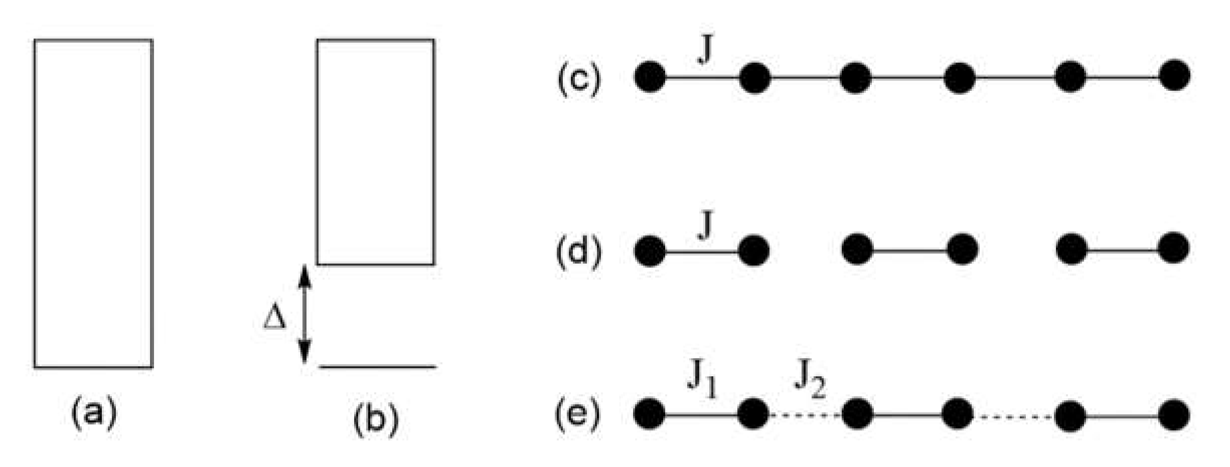
Figure 1.
(a,b) Allowed energy states of a magnetic solid. Between the lowest-lying excited state and the ground state, there is no energy gap in (a), but a non-zero energy gap in (b). (c–e) Examples of simple spin lattices: a uniform chain in (c); isolated spin dimers in (d); and an alternating chain in (e). Here, all nearest-neighbor spins are antiferromagnetically coupled.
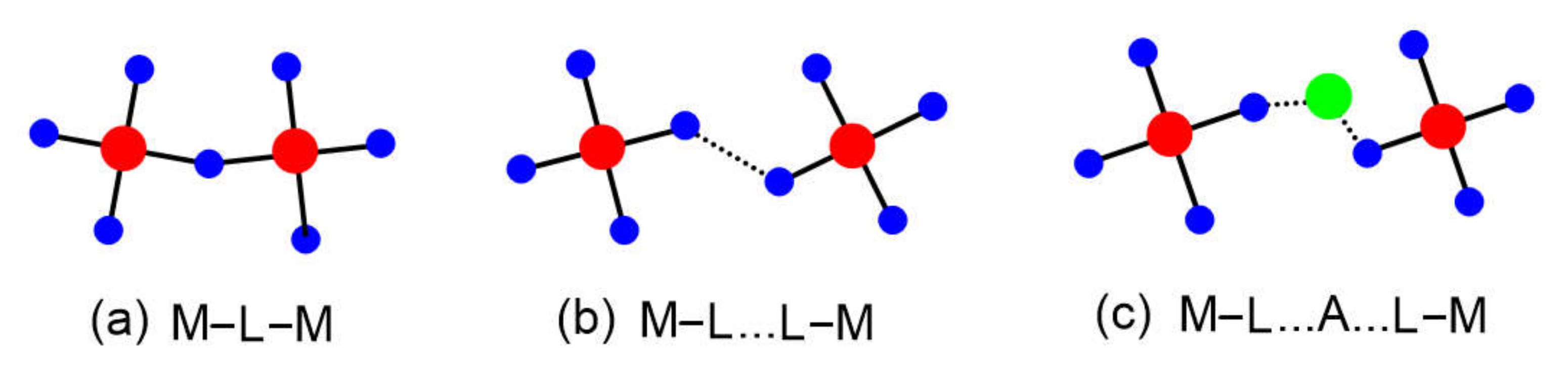
Figure 2.
Three types of spin exchange paths associated with two magnetic ions: (a) M–L–M, (b) M–L…L–M, and (c) M–L…A…L–M, where A represents a d0 cation such as V5+ or W6+. The M, L, and A are represented by red, blue, and green circles, respectively.
Figure 2.
Three types of spin exchange paths associated with two magnetic ions: (a) M–L–M, (b) M–L…L–M, and (c) M–L…A…L–M, where A represents a d0 cation such as V5+ or W6+. The M, L, and A are represented by red, blue, and green circles, respectively.
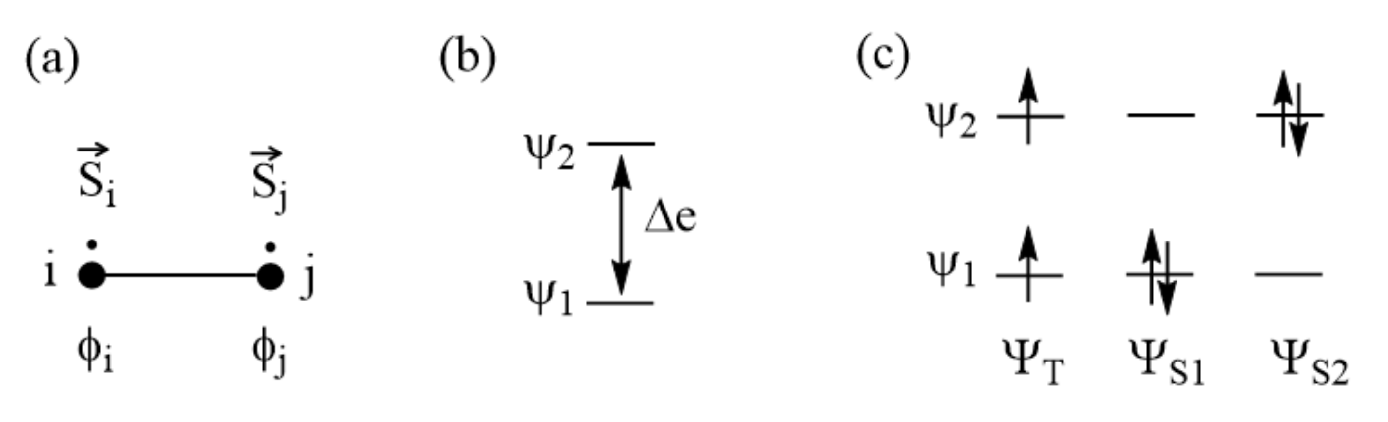
Figure 3.
(a) Spin dimer made up of two S = 1/2 ions at sites i and j. Each site has one unpaired spin. The magnetic orbitals at the sites i and j are represented by ϕi and ϕj, respectively. (b) The bonding and antibonding states, Ψ1 and Ψ2, resulting from the interactions between ϕi and ϕj, are split in energy by Δe. (c) The singlet and triplet electron configurations resulting from Ψ1 and Ψ2.
Figure 4.
Relationships of the spin exchange J to the energy difference between two spin states of a spin dimer made up of two S = 1/2 ions in terms of (a) the eigenstates and (b) the broken-symmetry states. The legends HS and BS in (b) refer to the high-symmetry and broken-symmetry states, respectively.
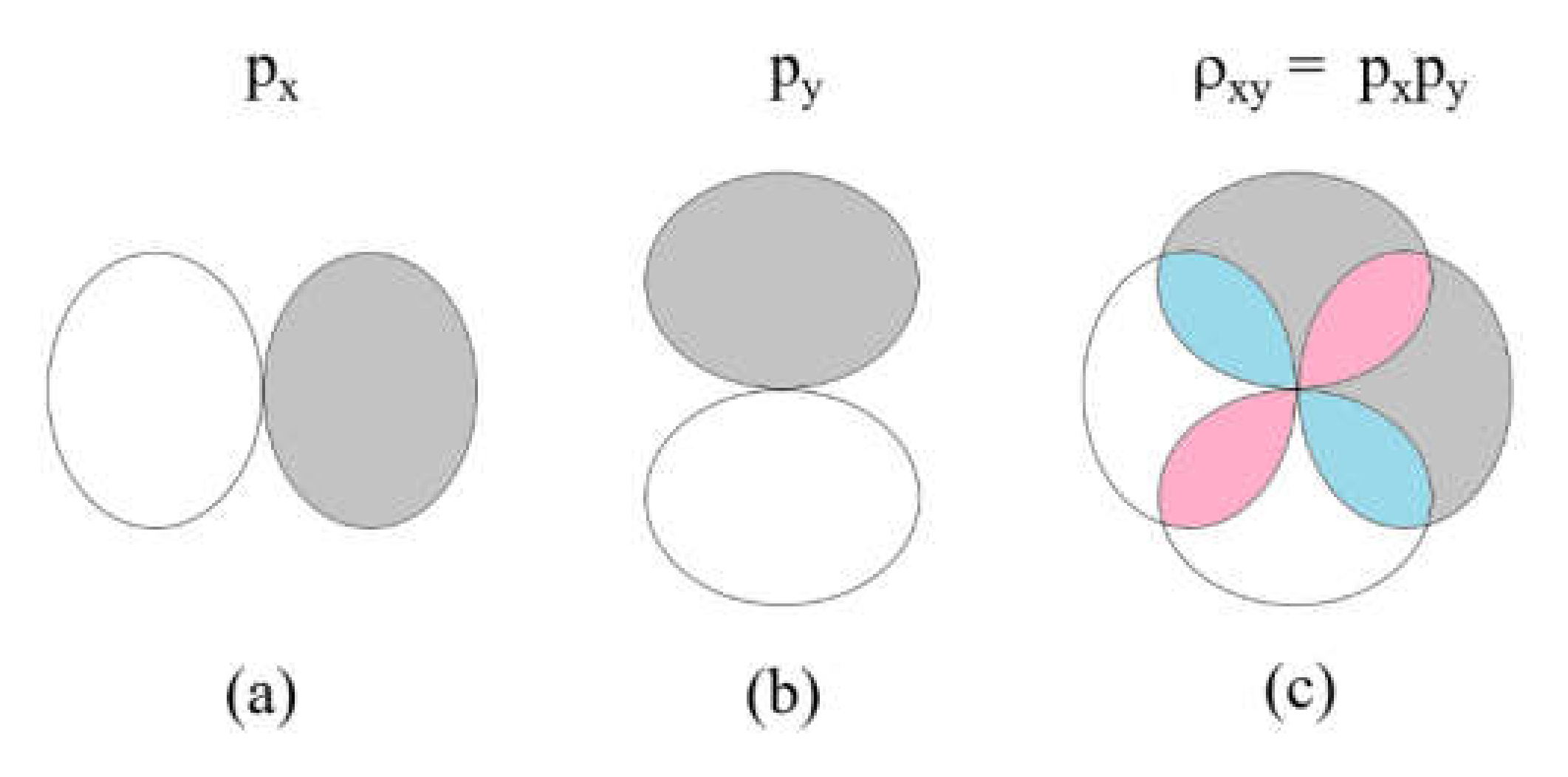
Figure 5.
The overlap density resulting from two p-orbital at a given atomic site: (a) a px orbital; (b) a py orbital; and (c) the overlap density between the two orbitals, . The pink and cyan regions have positive and negative values, respectively.
Figure 5.
The overlap density resulting from two p-orbital at a given atomic site: (a) a px orbital; (b) a py orbital; and (c) the overlap density between the two orbitals, . The pink and cyan regions have positive and negative values, respectively.
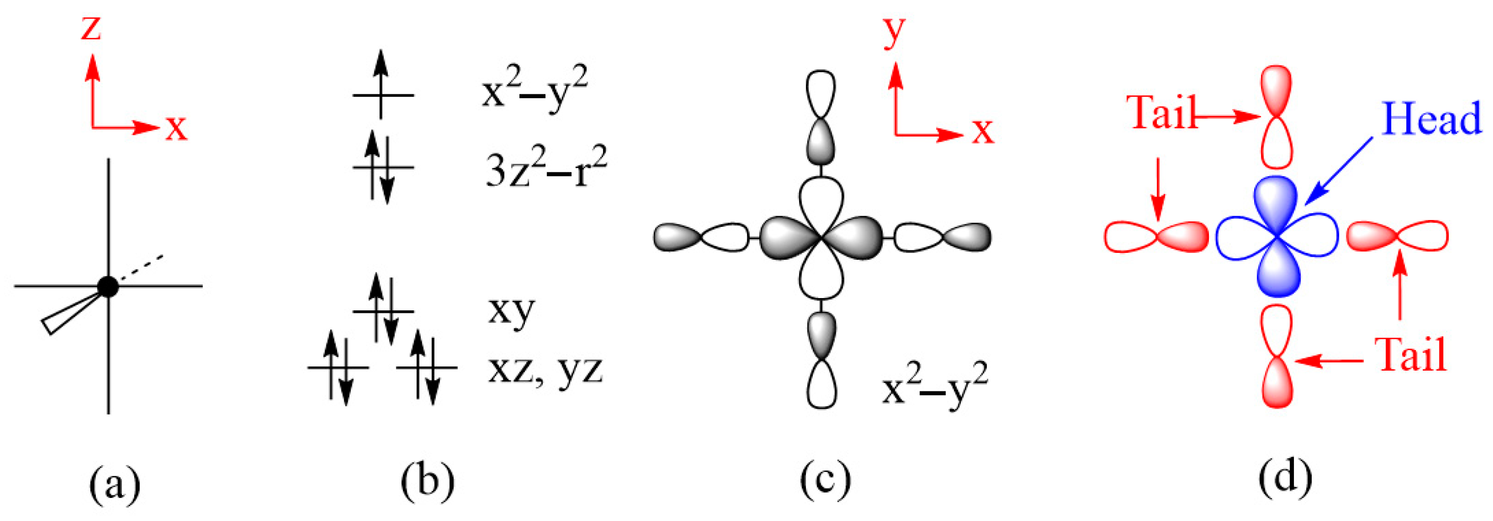
Figure 6.
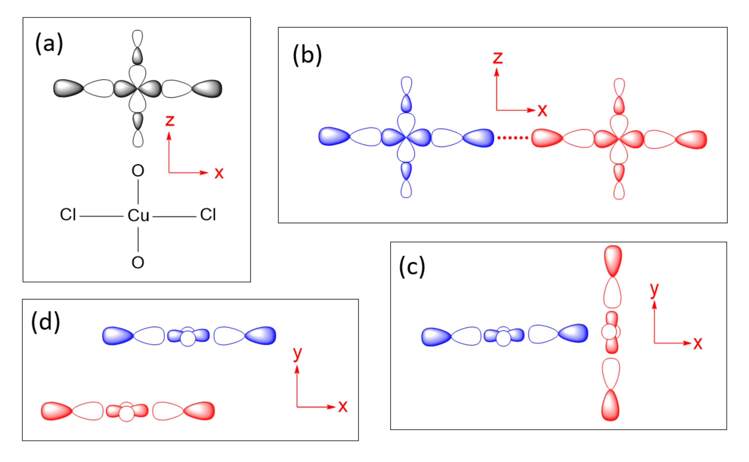
(a) An axially elongated CuL6 octahedron. (b) The electron configuration of a Cu2+(d9) ion at an axially elongated octahedral site. (c) The magnetic orbital of the Cu2+(d9) ion at an axially elongated octahedral site, which is contained in the CuL4 equatorial plane. (d) The head and tails of the magnetic orbital.
Figure 6.
(a) An axially elongated CuL6 octahedron. (b) The electron configuration of a Cu2+(d9) ion at an axially elongated octahedral site. (c) The magnetic orbital of the Cu2+(d9) ion at an axially elongated octahedral site, which is contained in the CuL4 equatorial plane. (d) The head and tails of the magnetic orbital.
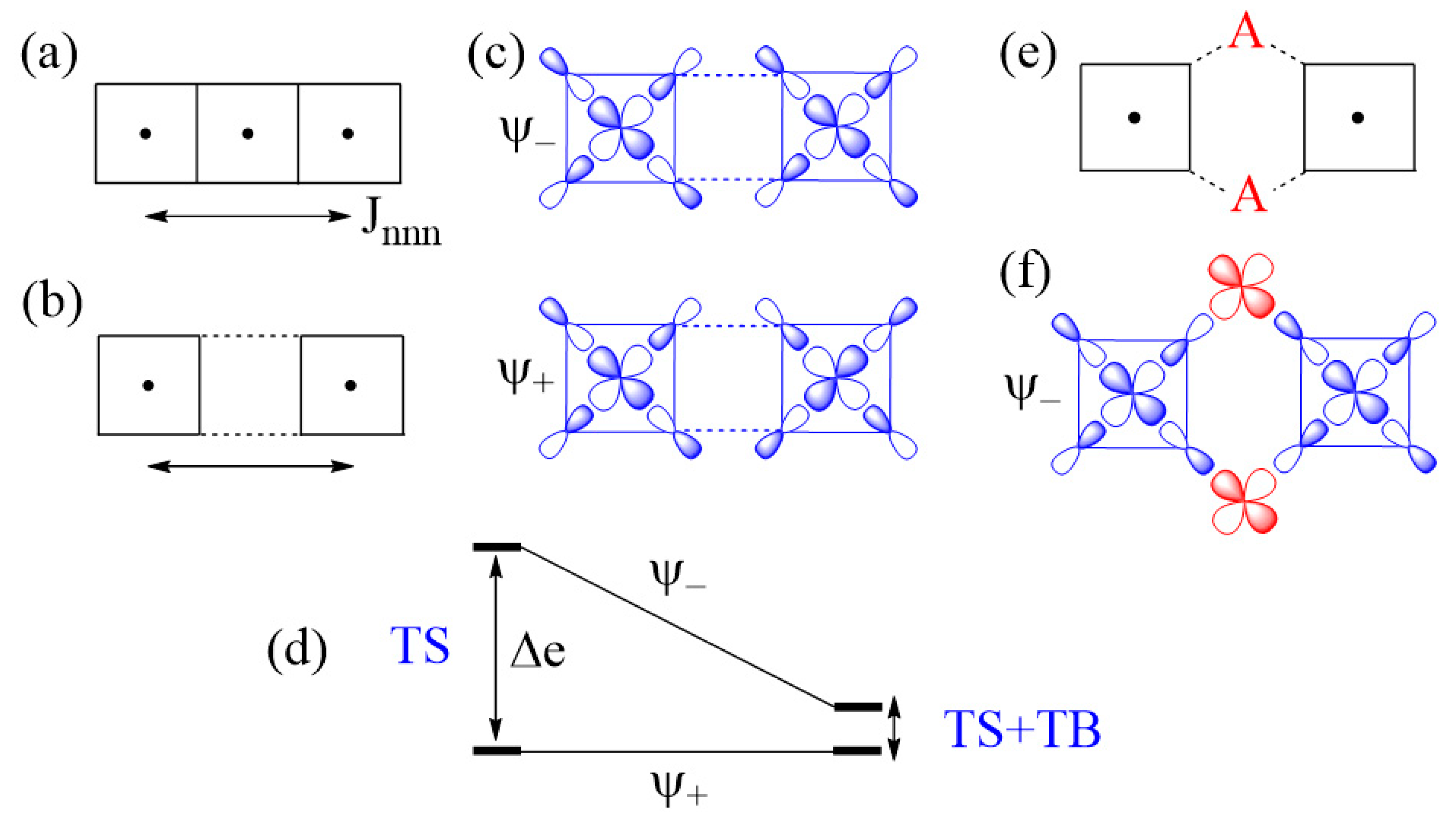
Figure 7.
(a) The next-nearest-neighbor spin exchange Jnnn in a CuL2 ribbon chain made up of edge-sharing CuL4 square planes. (b) A case of strong Cu–L…L–Cu exchange, which represents the next-nearest-neighbor exchange Jnnn. (c) The in-phase and out-of-phase combinations of the two magnetic orbitals,
and , respectively, associated with the Cu–L…L–Cu exchange. (d) The large energy split Δe resulting from the through-space (TS) interaction in the Cu–L…L–Cu exchange becomes small in the Cu–L…A…L–Cu exchange as a result of the through-bond (TB) interaction that occurs with the state. (e) A Cu–L…A…L–Cu exchange generated when each L…L contact is bridged by a d0 metal cation A. (f) The bonding interaction of the state with the dπ orbital of A.
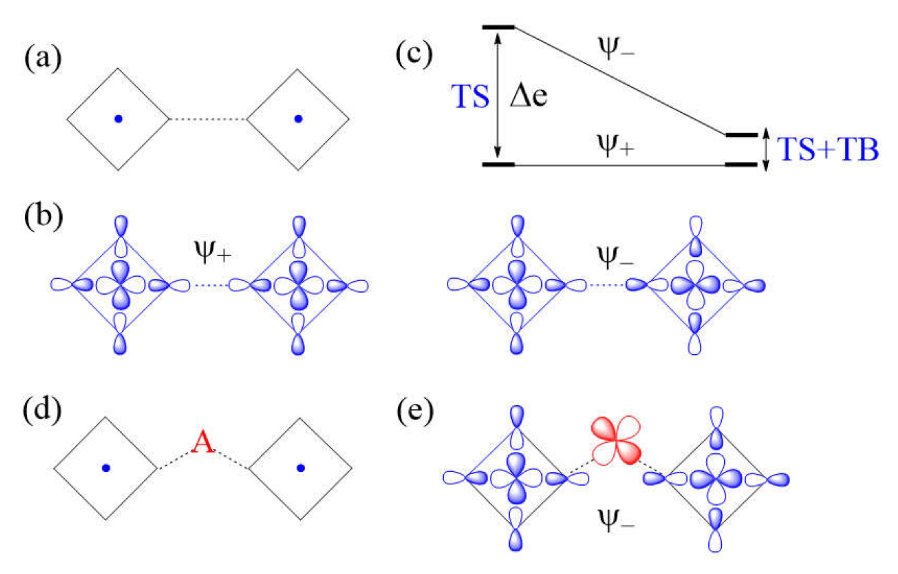
Figure 8.
(a) A case of strong Cu–L…L–Cu spin exchange where the two Cu–L bonds leading to the L…L contacts are linear. (b) The in-phase and out-of-phase combinations (
and , respectively) of the two magnetic orbitals, resulting from the through-space (TS) interactions. (c) The energy split Δe between and is large when the overlap between the p-orbital tails is large. (d) A Cu–L…A…L–Cu exchange generated when the L…L contact is bridged by a d0 metal cation A. (e) The bonding interaction of the state with the dπ orbital of A. (f) The large energy split Δe resulting from the through-space (TS) interaction in the Cu–L…L–Cu exchange becomes small in the Cu–L…A…L–Cu exchange as a result of the through-bond (TB) interaction that occurs primarily with the state.
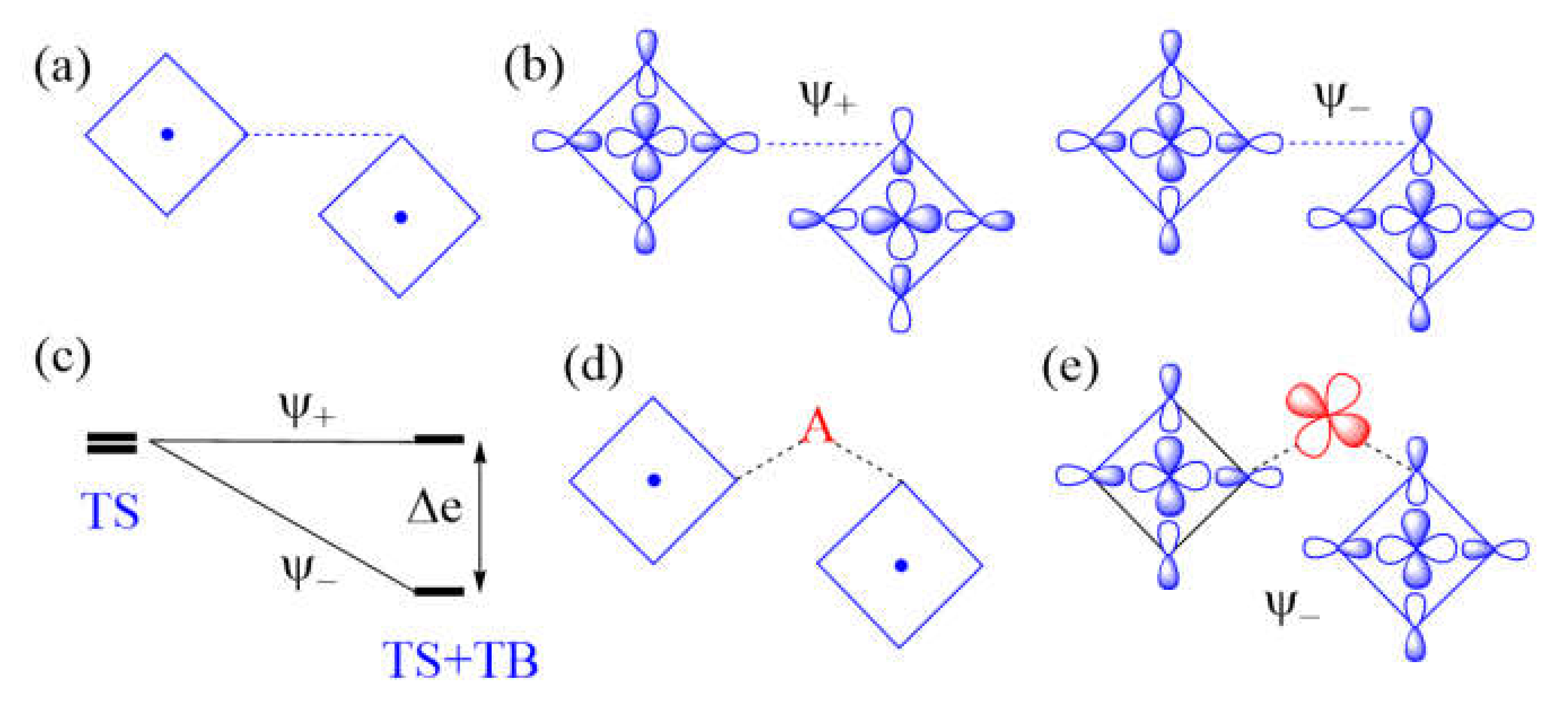
Figure 9.
(a) A case of weak Cu–L…L–Cu spin exchange, where the two Cu–L bonds leading to the L…L contacts are orthogonal. (b) The in-phase and out-of-phase combinations (
and , respectively) of the two magnetic orbitals. (c) The vanishing energy split Δe resulting from the through-space (TS) interaction in the Cu–L…L–Cu exchange is enhanced in the Cu–L…A…L–Cu exchange as a result of the through-bond (TB) interaction that occurs primarily with the state. (d) A Cu–L…A…L–Cu exchange generated when the L…L contact is bridged by a d0 metal cation A. (e) The in-phase interaction of the state with the dπ orbital of A.
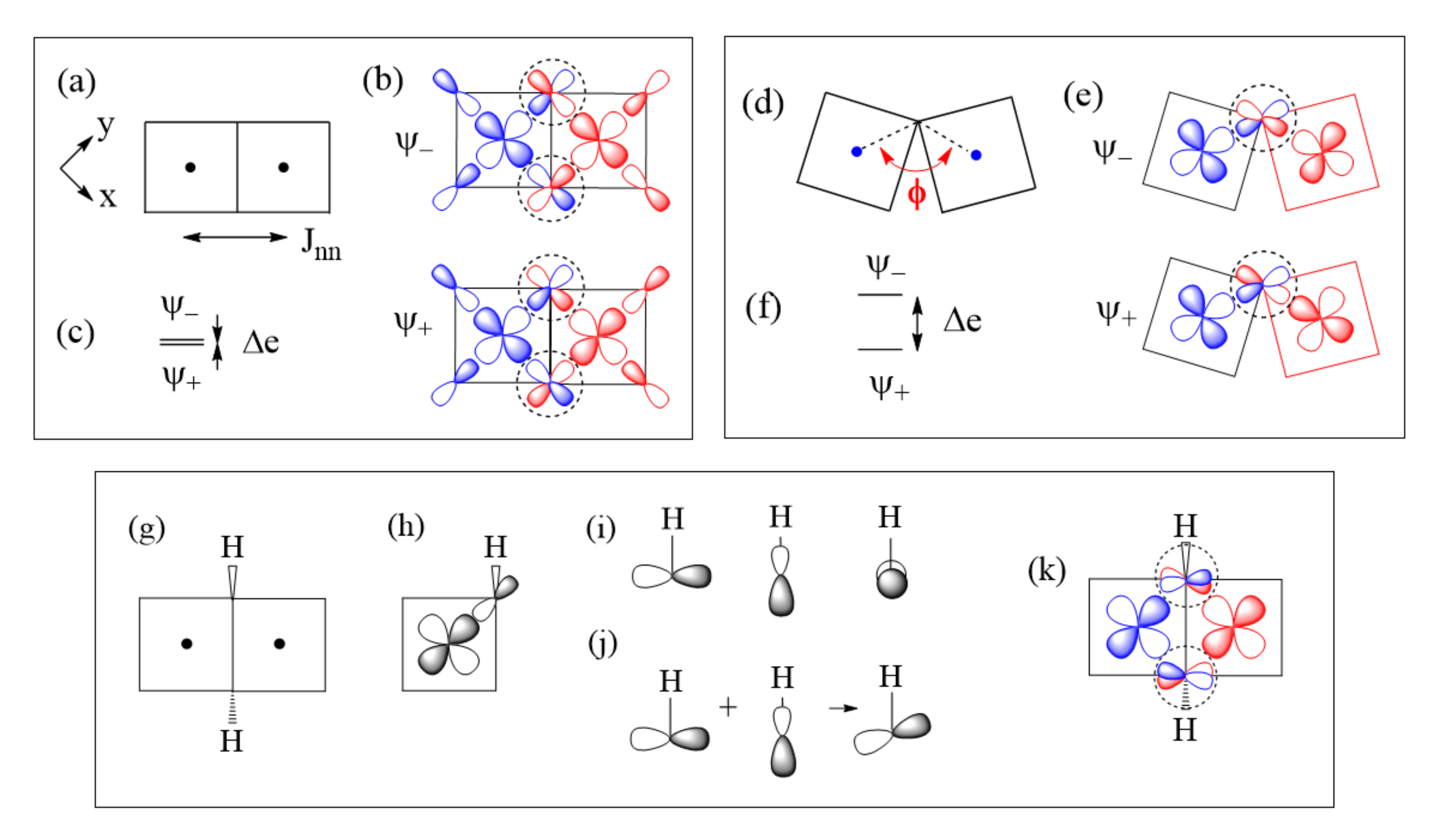
Figure 10.
(a–c) A Cu–L–Cu spin exchange with ∠M–L–M angle ϕ = 90°: This occurs in a Cu2L6 dimer shown in (a), which is made up of two coplanar CuL4 square planes by sharing an edge. The in-phase and out-of-phase combinations of the two magnetic orbitals in (b), and the energy split Δe between the two in (c). (d–f) A Cu–L–Cu spin exchange with ∠M–L–M angle ϕ > 90°: This occurs when two non-coplanar CuL4 square planes are corner-shared as in (d). The in-phase and out-of-phase combinations of the two magnetic orbitals in (e), and the energy split Δe between the two in (f). (g–k) Effect of the molecular anions OH− on the spin exchange of the edge-sharing Cu2O6 dimer: the shared edge consists of two OH− ions in (g); the p-orbital tail of one OH− ligand in a CuO4 square plane expected if the OH− is treated as O2− in (h); the three oxygen lone pairs associated with an isolated OH− in (i); the tilting of the O 2p-orbital tail by mixing two oxygen lone pairs in (j); and the arrangement of the tilted O 2p-tails at the bridging O atoms of the Cu2O6 dimer in (k).
![Molecules 26 00531 g010]()
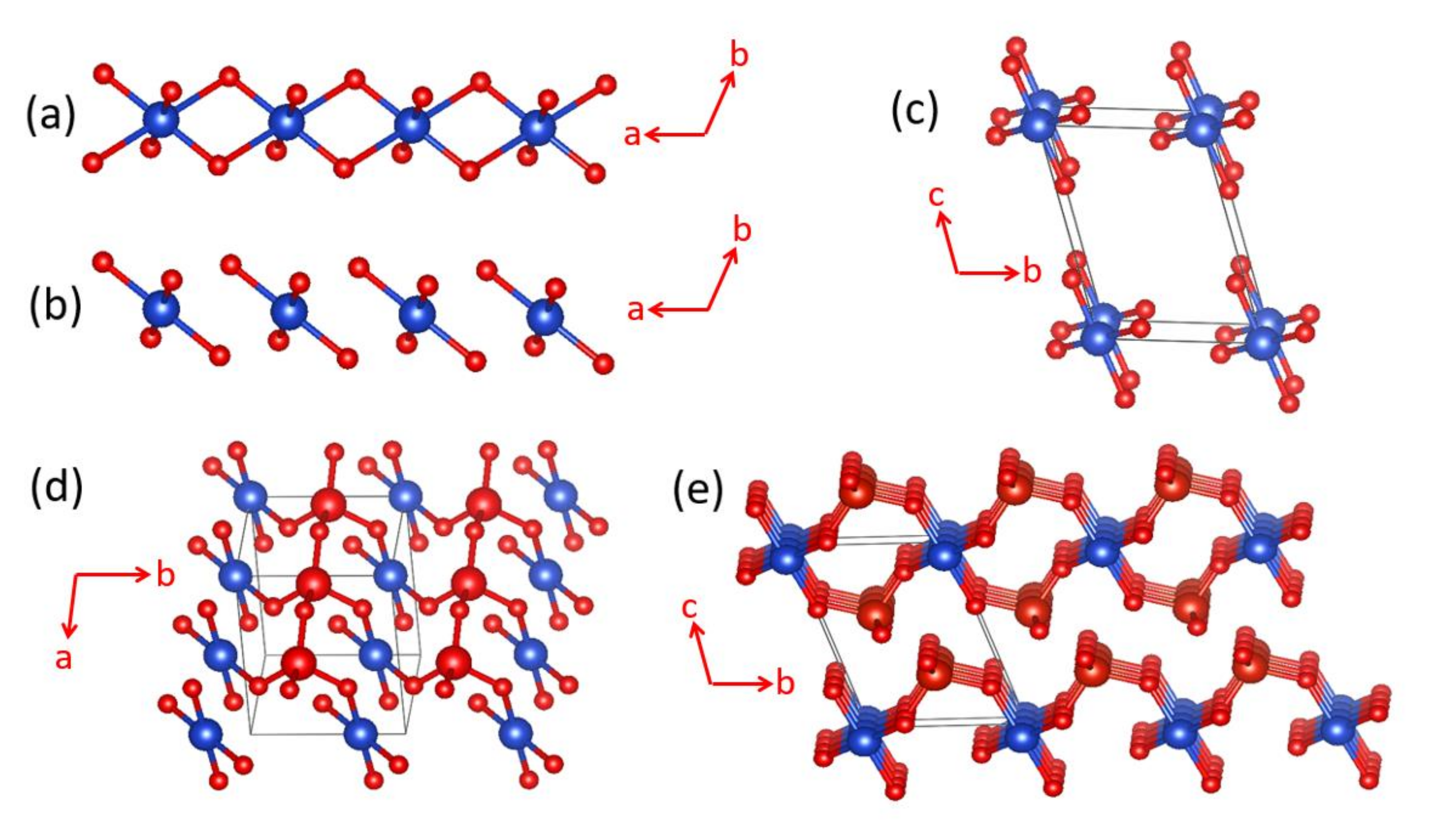
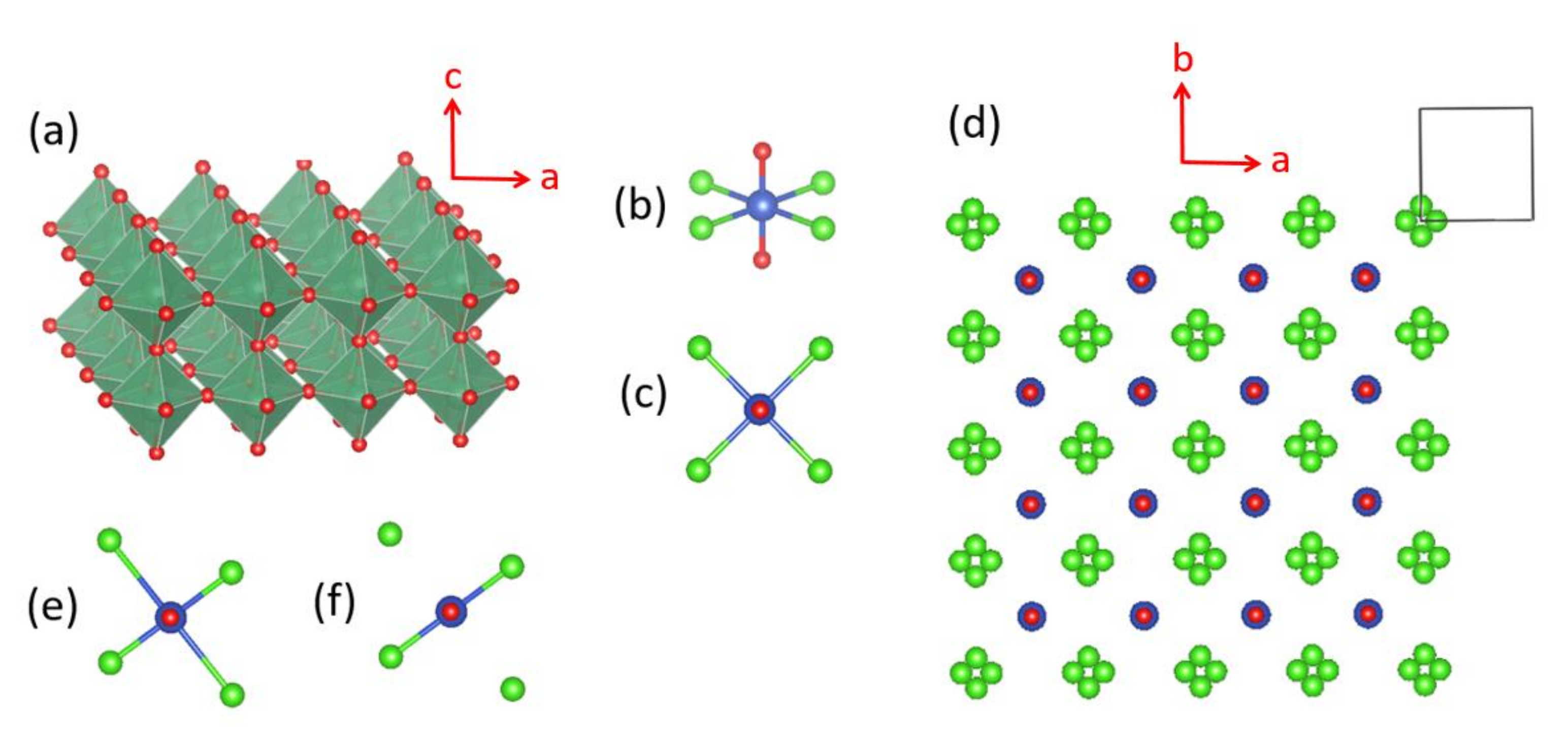
Figure 11.
Crystal structure of α-CuV2O6, where the blue spheres represent the Cu atoms, and the large and small red spheres the V and O atoms, respectively: (a) A CuO4 chain along the a-direction, which is made up of edge-sharing, axially-elongated, CuO6 octahedra. (b) A stack of CuO4 square planes along the a-direction, which results from the chain of edge-sharing CuO6 octahedra by removing the axial Cu-O bonds. (c) Stacks of CuO4 square planes running along the c-direction. (d) One sheet of CuO4 stack chains parallel to the a–b plane condensed with chains of corner-sharing VO4 tetrahedra on one side of the sheet. (e) Stacking of CuV2O6 layers forming α-CuV2O6.
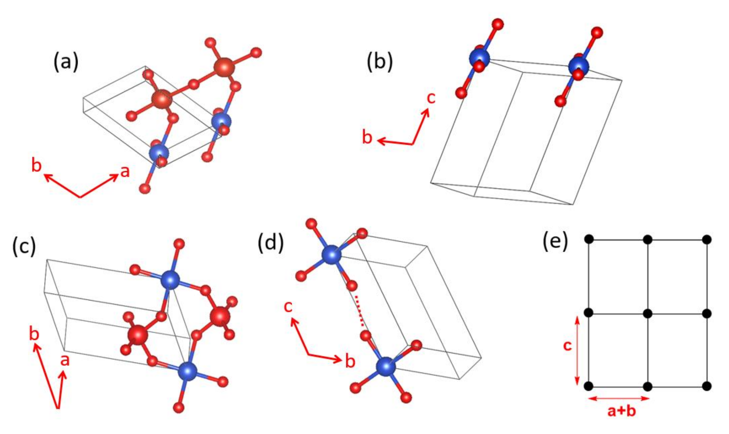
Figure 12.
Spin exchange paths and spin lattice of α-CuV2O6: (a) Spin exchange along the b-direction, Jb; (b) Spin exchange along the c-direction, Jc; (c) Spin exchange along the a-direction, Ja; (d) Spin exchange along the (a + b)-direction, Ja+b; (e) Rectangular spin lattice made up of Jc and Ja+b.
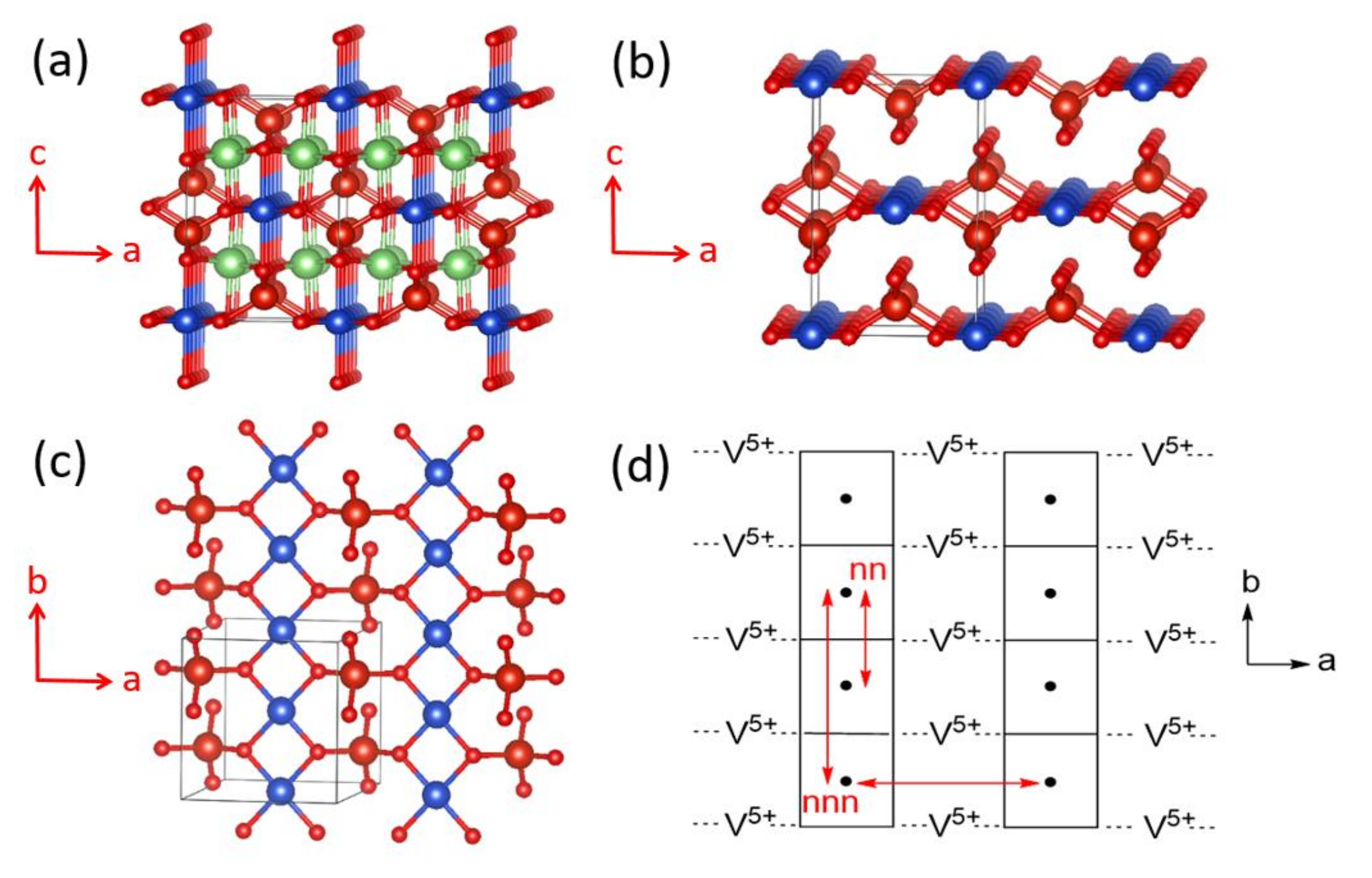
Figure 13.
(a) The crystal structure of LiCuVO4 viewed approximately along the b-direction, where the blue and green spheres represent the Cu and Li atoms, respectively, and the large and small red spheres represent the V and O atoms, respectively. (b) The CuVO4 lattice resulting from LiCuVO4 by removing the axial Cu–O bonds and Li atoms. (c) A perspective view of a single CuVO4 layer approximately along the c-direction. (d) The spin exchange paths present in a single CuVO4 layer, where the labels nn, nnn and a represent the spin exchanges Jnn, Jnnn and Ja, respectively.
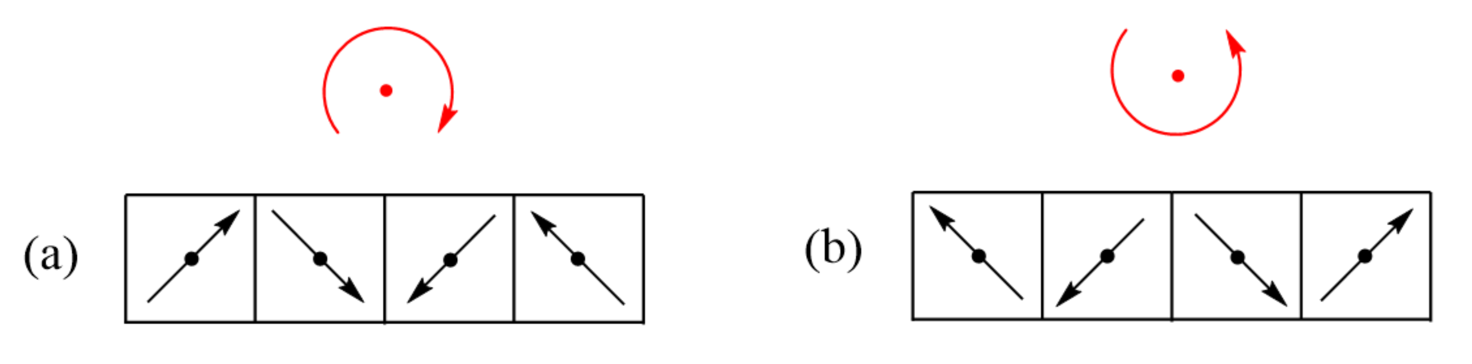
Figure 14.
(a,b) Two cycloids, which are opposite in chirality but are identical in energy.
Figure 14.
(a,b) Two cycloids, which are opposite in chirality but are identical in energy.
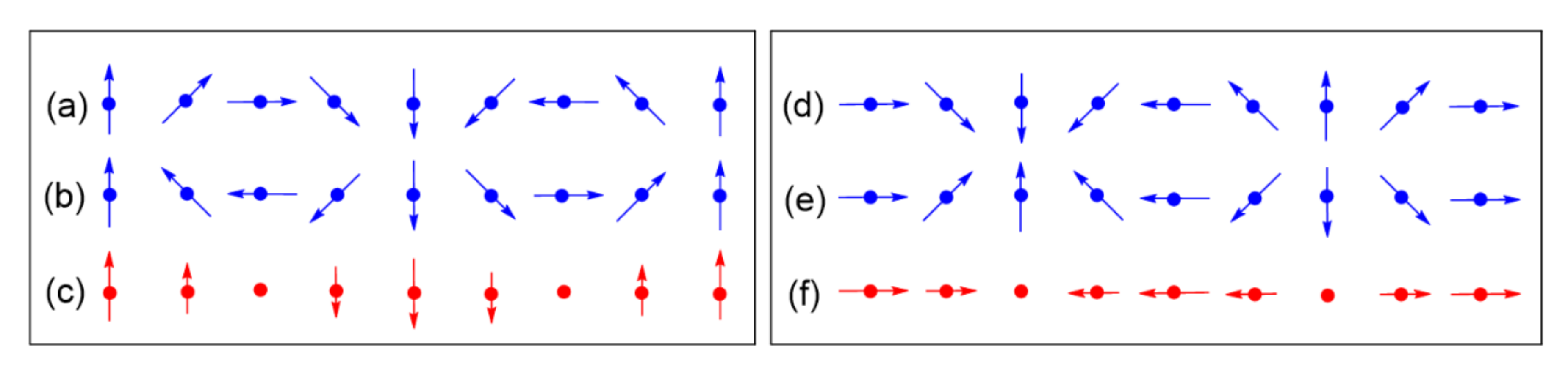
Figure 15.
The superposition of the two chiral cycloids in (a); (b) leads to the transverse SDW in (c). The superposition of the two chiral cycloids in (d); (e) leads to the longitudinal SDW in (f). For ease of illustration, the angle of the spin rotation was taken to be 45°.
Figure 15.
The superposition of the two chiral cycloids in (a); (b) leads to the transverse SDW in (c). The superposition of the two chiral cycloids in (d); (e) leads to the longitudinal SDW in (f). For ease of illustration, the angle of the spin rotation was taken to be 45°.
Figure 16.
(a) One LaNb2O7 layer of tetragonal (CuCl)LaNb2O7, where the La atoms at the 12 coordinate sites formed by eight corner-sharing NbO6 octahedra are not shown for simplicity. (b) Perspective and (c) projection views of a CuCl4O2 octahedron with 4-fold rotational symmetry around the O–Cu–O axis aligned along the c-direction. (d) A projection view of a CuClO2 layer of tetragonal (CuCl)LaNb2O7 in which every Cl site is split into four positions. (e,f) Projection views of the Jahn–Teller distorted CuCl4O2 octahedron, where the axially elongated Cu–Cl bonds are shown in (e), but are not shown in (f) for simplicity.
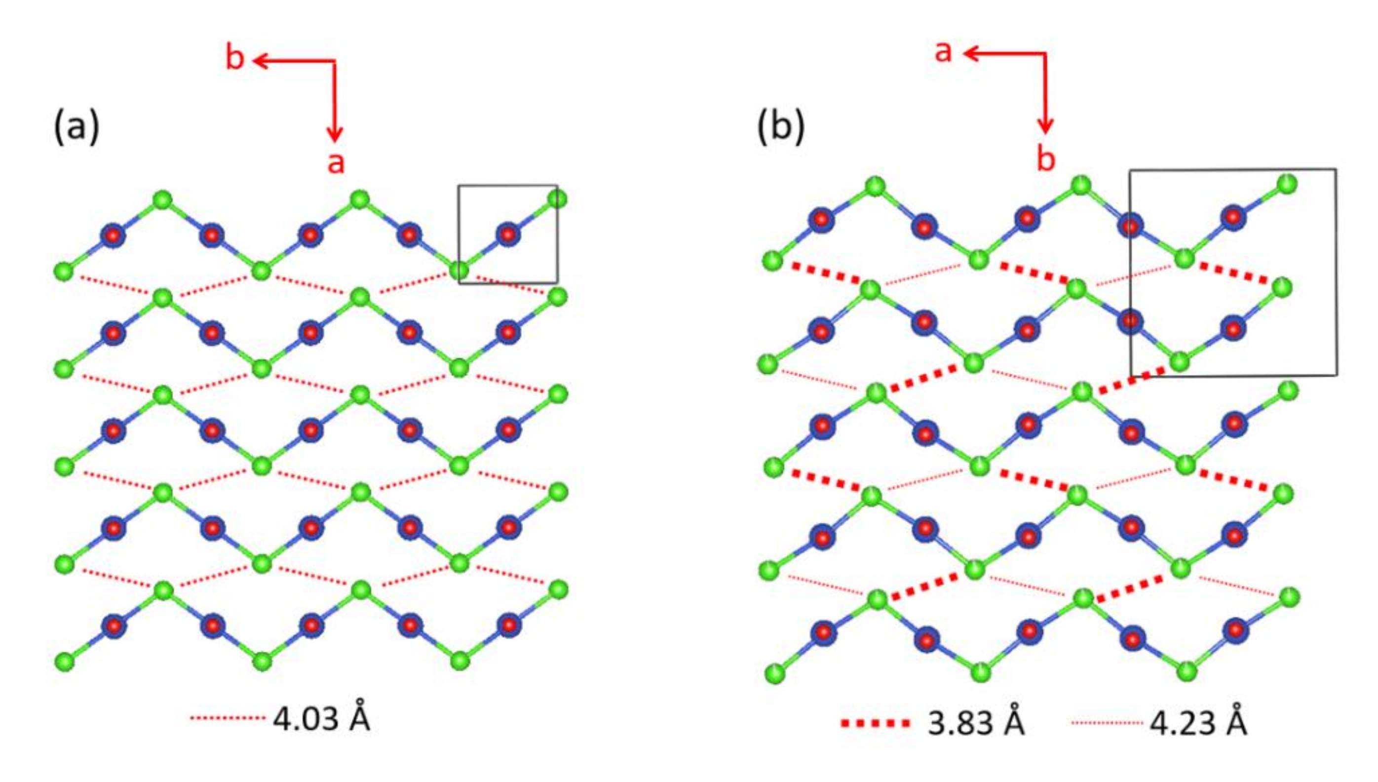
Figure 17.
The structures of the CuClO2 layer with cooperative Jahn–Teller distortion in (a) the tetragonal and (b) orthorhombic phases of (CuCl)LaNb2O7. The Cl–Cu–Cl unit is linear in the tetragonal structure, but is slightly bent in the orthorhombic structure. The latter has an important consequence on the spin exchanges.
Figure 18.
(a) The magnetic orbital lying in the CuCl2O2 rhombus plane, which is best described as the x2–z2 state. (b–d) Three different types of the magnetic orbital arrangements found in the CuClO2 layers of orthorhombic CuCl(LaV2O7). In this idealized representation of the CuCl2O2 rhombus, the slight bending of the Cl–Cu–Cl linkage is neglected for clarity.
Figure 19.
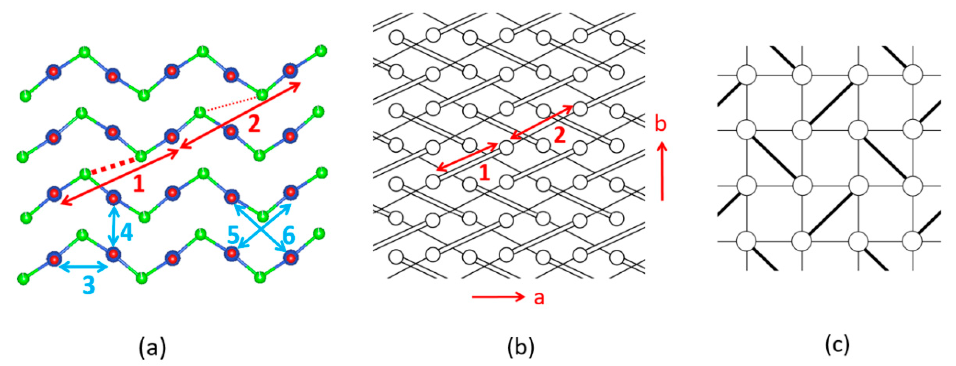
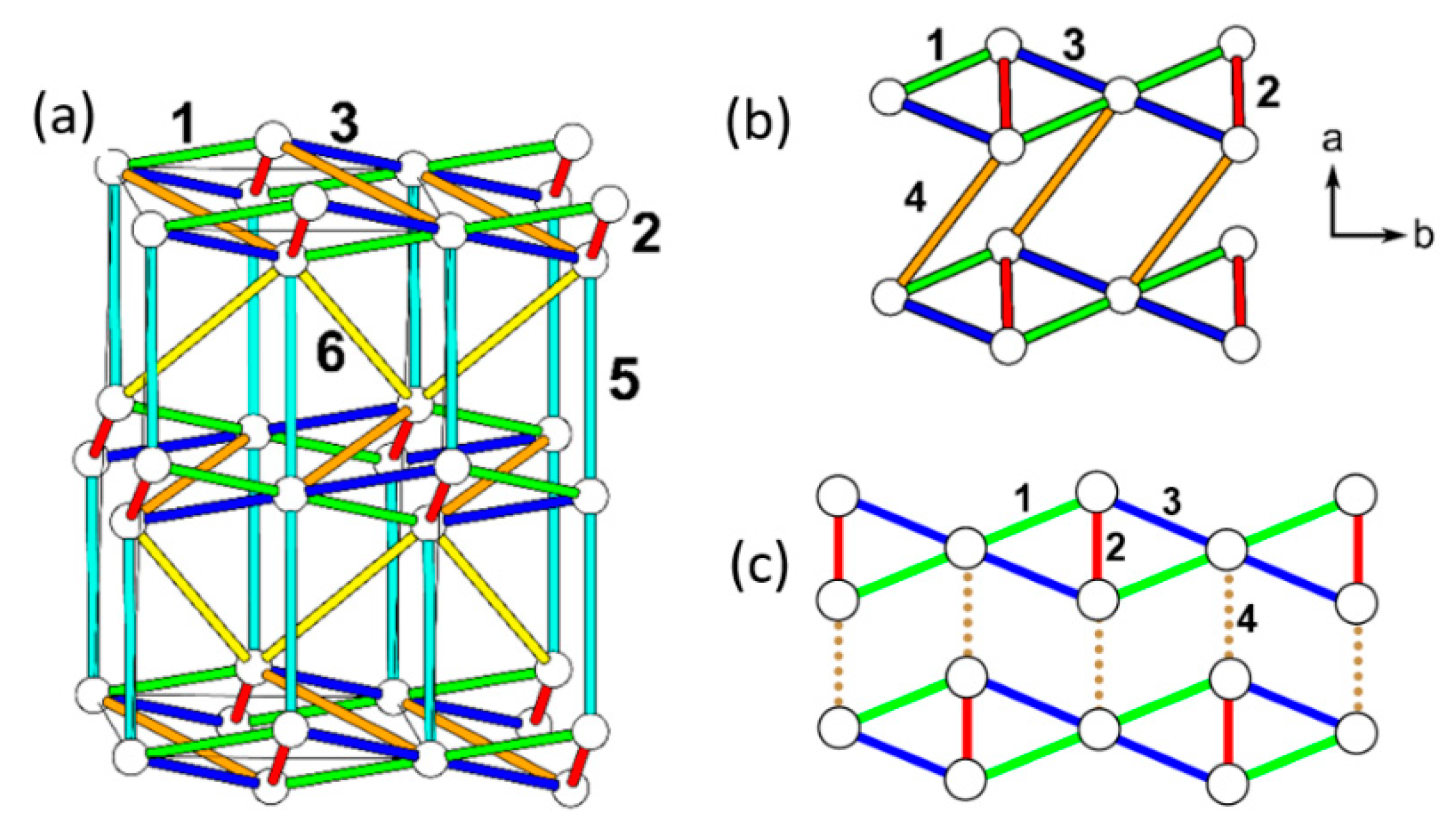
(a) Six spin exchange paths of the CuClO2 layer in orthorhombic CuCl(LaV2O7), and the numbers 1–6 refer to J1–J6, respectively. (b) The J1–J2 AFM alternating chains the CuClO2 layer. Only the Cu2+ ions are shown as empty circles, with J1 and J2 paths represented by cylinders and lines, respectively. (c) The simplified spin lattice of the CuClO2 layer generated by the three strongest spin exchanges, which is the Shastry–Sutherland spin lattice.
Figure 19.
(a) Six spin exchange paths of the CuClO2 layer in orthorhombic CuCl(LaV2O7), and the numbers 1–6 refer to J1–J6, respectively. (b) The J1–J2 AFM alternating chains the CuClO2 layer. Only the Cu2+ ions are shown as empty circles, with J1 and J2 paths represented by cylinders and lines, respectively. (c) The simplified spin lattice of the CuClO2 layer generated by the three strongest spin exchanges, which is the Shastry–Sutherland spin lattice.
Figure 20.
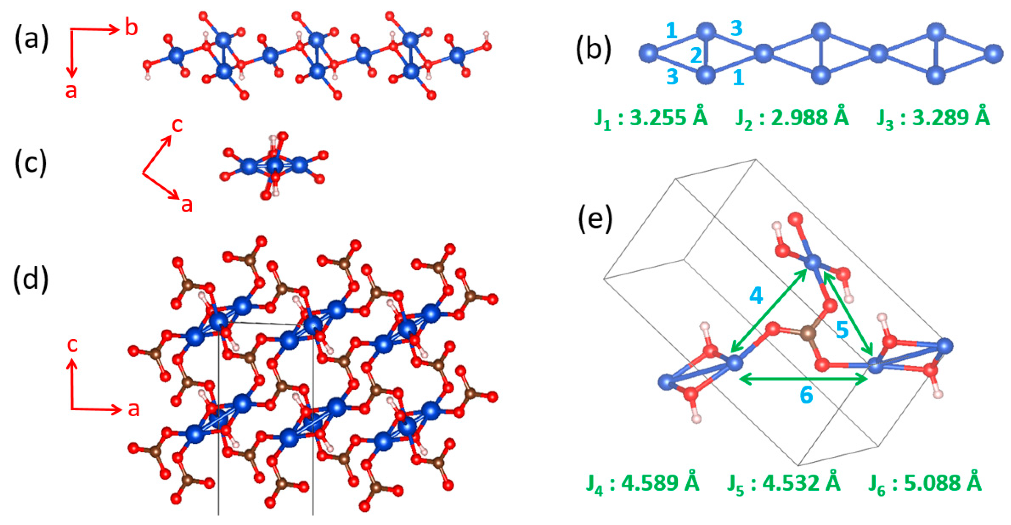
(a) The diamond chain made up of CuO4 square planar units. (b) Definition of the three spin exchanges J1–J3 in a diamond chain. (c) A projection view of the diamond chain along the chain direction. (d) The structure of Azurite viewed along the diamond chain direction. (e) Definition of the three spin exchanges J4–J6 between adjacent diamond chains.
Figure 20.
(a) The diamond chain made up of CuO4 square planar units. (b) Definition of the three spin exchanges J1–J3 in a diamond chain. (c) A projection view of the diamond chain along the chain direction. (d) The structure of Azurite viewed along the diamond chain direction. (e) Definition of the three spin exchanges J4–J6 between adjacent diamond chains.
Figure 21.
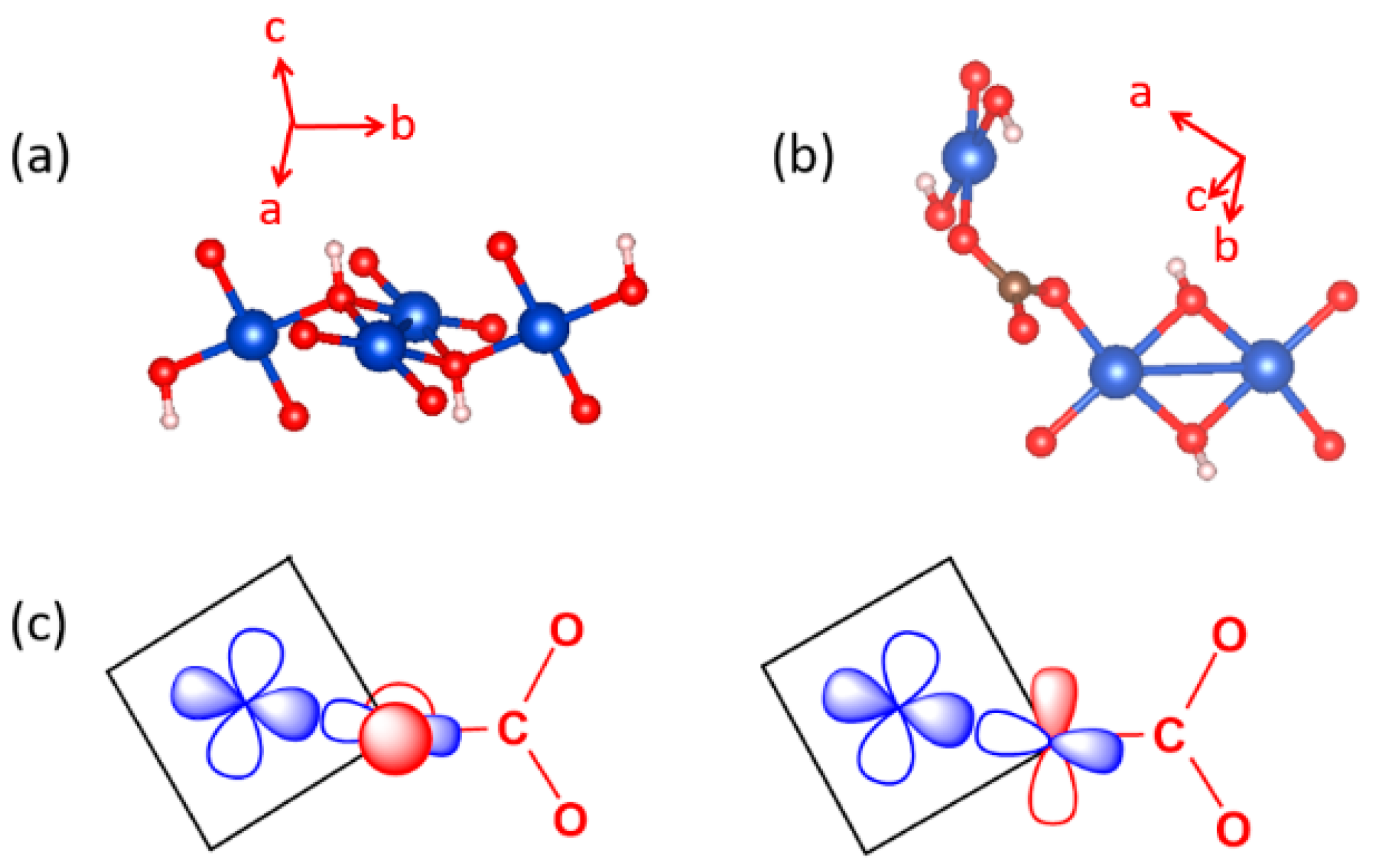
(a) A diamond unit of Azurite. (b) Arrangement of the CuO4 monomer and Cu2O6 dimer associated with the spin exchange path J4. (c) Interaction of the O pπ and O pσ orbitals of the CO32− ion with the p-orbital tail of the Cu2+ ion magnetic orbital.
Figure 21.
(a) A diamond unit of Azurite. (b) Arrangement of the CuO4 monomer and Cu2O6 dimer associated with the spin exchange path J4. (c) Interaction of the O pπ and O pσ orbitals of the CO32− ion with the p-orbital tail of the Cu2+ ion magnetic orbital.
Figure 22.
(a) Arrangement of the spin exchange paths J1–J6 in Azurite. (b) Arrangement of the four strongest spin exchanges J1–J4 in Azurite. (c) 2D spin lattice describing Azurite.
Figure 22.
(a) Arrangement of the spin exchange paths J1–J6 in Azurite. (b) Arrangement of the four strongest spin exchanges J1–J4 in Azurite. (c) 2D spin lattice describing Azurite.
Table 1.
Values of the spin exchanges J1–J6 determined by DFT+U calculations with Ueff = 4 and 5 eV.
Table 1.
Values of the spin exchanges J1–J6 determined by DFT+U calculations with Ueff = 4 and 5 eV.
| | Ueff = 4 | Ueff = 5 |
|---|
| J2 | 241.5 K | 194.6 K |
| J3/J2 | 0.28 | 0.27 |
| J1/J2 | 0.21 | 0.19 |
| J4/J2 | 0.17 | 0.16 |
| J5/J2 | −0.01 | −0.02 |
| J6/J2 | 0.04 | 0.03 |


