
Recent Development of Tunable Optical Devices Based on Liquid

Abstract
:1. Introduction
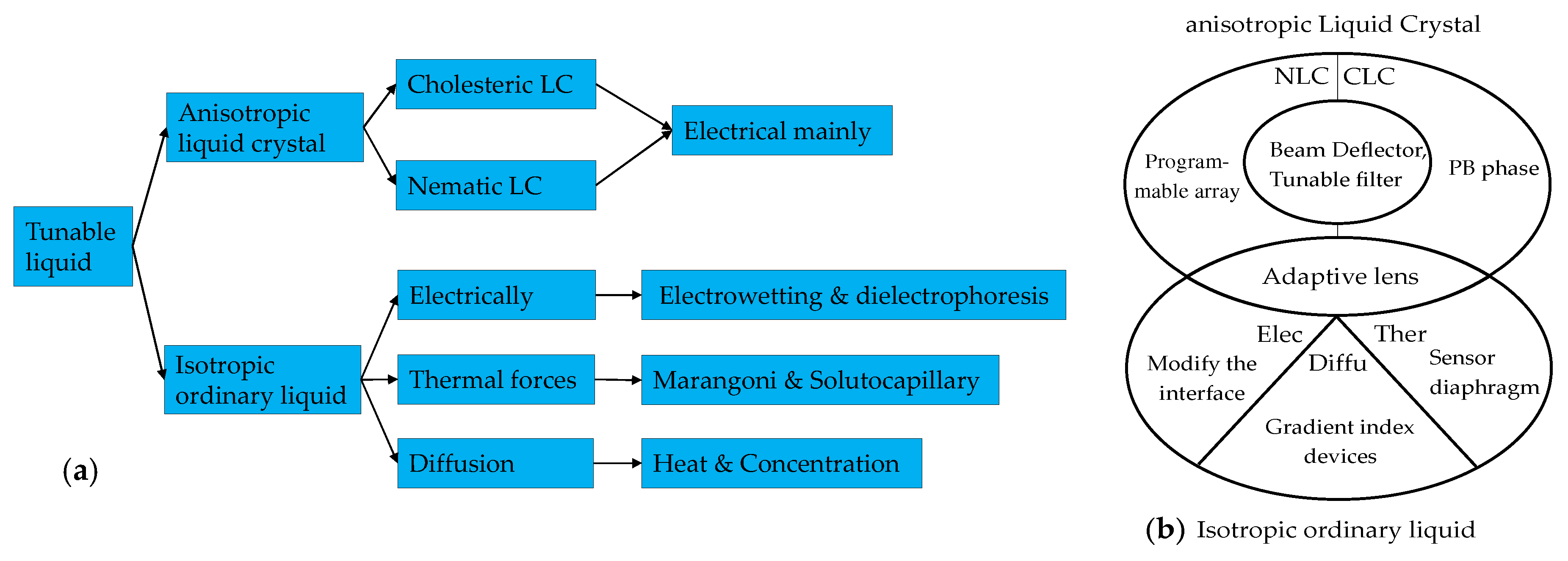
2. Principles of Liquid Optics Control
2.1. Liquid Crystal Control
2.1.1. Liquid Crystal Material
2.1.2. Liquid Crystal Alignment Technology
- micro-polarizer array using photoalignment technology for image sensors;
- electrically tunable liquid crystal q-plates;
- electrically switchable liquid crystal Fresnel lens and gratings;
- liquid crystal optical elements with integrated Pancharatnam–Berry phases.
2.2. Conventional Liquid Devices Control
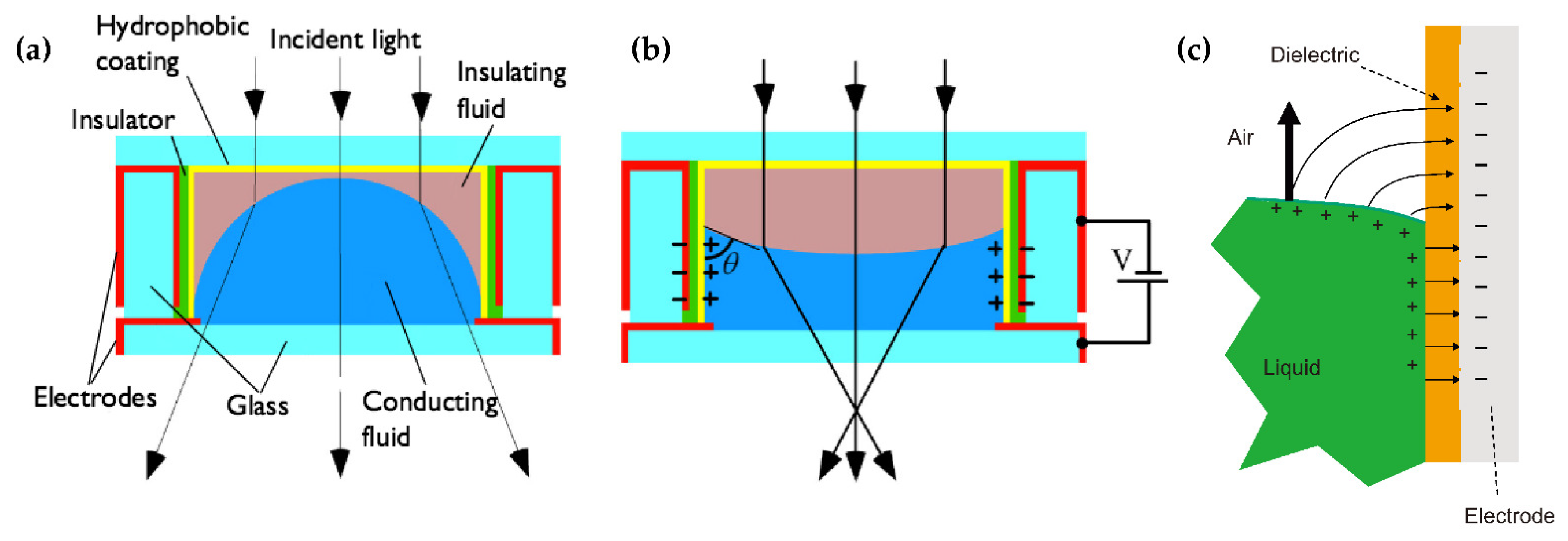
2.2.1. Interface Control
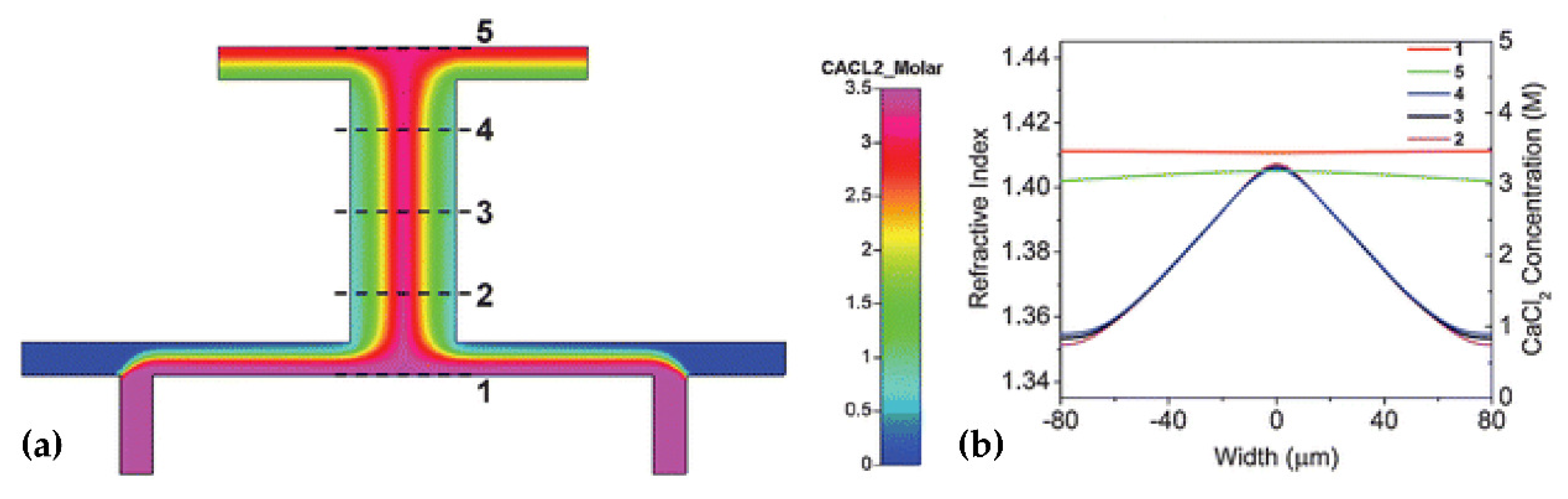
2.2.2. Refractive Index Profile Due to Diffusion
3. Tunable Devices Based on Liquid Crystal
3.1. Tunable Lens
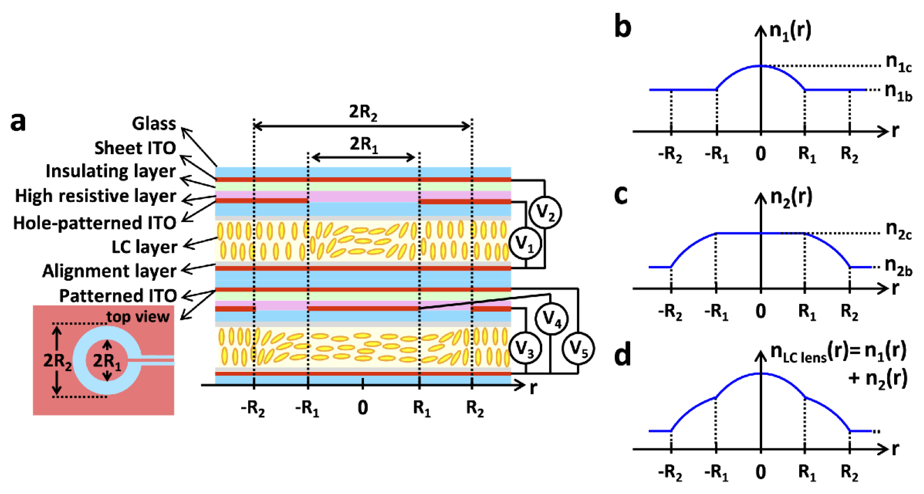
3.1.1. Model Liquid Crystal Lens
3.1.2. Pattern Electrode
3.2. Tunable Filter and Absorber
3.2.1. Visible Light to Infrared
3.2.2. THz Absorber and Filter Based on Meta-Material
3.3. Tunable Beam Controller
3.3.1. Beam Deflection Control
3.3.2. Laser Polarization Mode
3.3.3. Optical Switch
5. Conclusions and the Future
Author Contributions
Funding
Institutional Review Board Statement
Informed Consent Statement
Data Availability Statement
Acknowledgments
Conflicts of Interest
Sample Availability
References
- Mutailipu, M.; Pan, S. Emergent Deep-Ultraviolet Nonlinear Optical Candidates. Angew. Chem. Int. Ed. 2020, 59, 20302–20317. [Google Scholar] [CrossRef]
- Mutailipu, M.; Poeppelmeier, K.R.; Pan, S. Borates: A Rich Source for Optical Materials. Chem. Rev. 2021, 121, 1130–1202. [Google Scholar] [CrossRef]
- Xu, S.; Ren, H.; Wu, S.-T. Dielectrophoretically Tunable Optofluidic Devices. J. Phys. D Appl. Phys. 2013, 46, 483001. [Google Scholar] [CrossRef]
- Oladepo, S.A. Development and Application of Liquid Crystals as Stimuli-Responsive Sensors. Molecules 2022, 27, 1453. [Google Scholar] [CrossRef]
- Wang, Z.; Zhang, Y.; Gong, X.; Yuan, Z.; Feng, S.; Xu, T.; Liu, T.; Chen, Y.-C. Bio-Electrostatic Sensitive Droplet Lasers for Molecular Detection. Nanoscale Adv. 2020, 2, 2713–2719. [Google Scholar] [CrossRef]
- **a, C.; Zhou, D.; Su, Y.; Zhou, G.; Yao, L.; Sun, W.; Liu, Y. A Liquid-Crystal-Based Immunosensor for the Detection of Cardiac Troponin I. Analyst 2020, 145, 4569–4575. [Google Scholar] [CrossRef]
- Wu, P.-C.; Karn, A.; Lee, M.-J.; Lee, W.; Chen, C.-Y. Dye-Liquid-Crystal-Based Biosensing for Quantitative Protein Assay. Dyes Pigment. 2018, 150, 73–78. [Google Scholar] [CrossRef]
- Wang, Y.; Zhou, L.; Kang, Q.; Yu, L. Simple and Label-Free Liquid Crystal-Based Sensor for Detecting Trypsin Coupled to the Interaction between Cationic Surfactant and BSA. Talanta 2018, 183, 223–227. [Google Scholar] [CrossRef]
- Kaur, J.; Singh, P.K. Trypsin Detection Strategies: A Review. Crit. Rev. Anal. Chem. 2022, 52, 949–967. [Google Scholar] [CrossRef]
- Yang, X.; Zhao, X.; Liu, F.; Li, H.; Zhang, C.X.; Yang, Z. Simple, Rapid and Sensitive Detection of Parkinson’s Disease Related Alpha-Synuclein Using a DNA Aptamer Assisted Liquid Crystal Biosensor. Soft Matter 2021, 17, 4842–4847. [Google Scholar] [CrossRef]
- Jau, H.-C.; Lin, T.-H.; Chen, Y.-Y.; Chen, C.-W.; Liu, J.-H.; Fuh, A.Y.-G. Direction Switching and Beam Steering of Cholesteric Liquid Crystal Gratings. Appl. Phys. Lett. 2012, 100, 131909. [Google Scholar] [CrossRef]
- Gao, Y.; Ding, W.; Lu, J. Templated Twist Structure Liquid Crystals and Photonic Applications. Polymers 2022, 14, 2455. [Google Scholar] [CrossRef]
- Lin, T.; **e, J.; Zhou, Y.; Zhou, Y.; Yuan, Y.; Fan, F.; Wen, S. Recent Advances in Photoalignment Liquid Crystal Polarization Gratings and Their Applications. Crystals 2021, 11, 900. [Google Scholar] [CrossRef]
- Alamro, F.S.; Gomha, S.M.; Shaban, M.; Altowyan, A.S.; Abolibda, T.Z.; Ahmed, H.A. Optical Investigations and Photoactive Solar Energy Applications of New Synthesized Schiff Base Liquid Crystal Derivatives. Sci. Rep. 2021, 11, 15046. [Google Scholar] [CrossRef]
- Chen, X.; Korblova, E.; Dong, D.; Wei, X.; Shao, R.; Radzihovsky, L.; Glaser, M.A.; Maclennan, J.E.; Bedrov, D.; Walba, D.M.; et al. First-Principles Experimental Demonstration of Ferroelectricity in a Thermotropic Nematic Liquid Crystal: Polar Domains and Striking Electro-Optics. Proc. Natl. Acad. Sci. USA 2020, 117, 14021–14031. [Google Scholar] [CrossRef]
- Sebastián, N.; Cmok, L.; Mandle, R.J.; de la Fuente, M.R.; Drevenšek Olenik, I.; Čopič, M.; Mertelj, A. Ferroelectric-Ferroelastic Phase Transition in a Nematic Liquid Crystal. Phys. Rev. Lett. 2020, 124, 037801. [Google Scholar] [CrossRef] [Green Version]
- Li, Q.; Green, L.; Venkataraman, N.; Shiyanovskaya, I.; Khan, A.; Urbas, A.; Doane, J.W. Reversible Photoswitchable Axially Chiral Dopants with High Helical Twisting Power. J. Am. Chem. Soc. 2007, 129, 12908–12909. [Google Scholar] [CrossRef]
- Zografopoulos, D.C.; Ferraro, A.; Beccherelli, R. Liquid-Crystal High-Frequency Microwave Technology: Materials and Characterization. Adv. Mater. Technol. 2018, 4, 1800447. [Google Scholar] [CrossRef]
- Zhou, Z.; Li, W.; Qian, J.; Liu, W.; Wang, Y.; Zhang, X.; Guo, Q.; Yashchyshyn, Y.; Wang, Q.; Shi, Y.; et al. Flexible Liquid Crystal Polymer Technologies from Microwave to Terahertz Frequencies. Molecules 2022, 27, 1336. [Google Scholar] [CrossRef]
- Kim, Y.; Tamaoki, N. Asymmetric Dimers of Chiral Azobenzene Dopants Exhibiting Unusual Helical Twisting Power upon Photoswitching in Cholesteric Liquid Crystals. ACS Appl. Mater. Interfaces 2016, 8, 4918–4926. [Google Scholar] [CrossRef]
- Ma, J.; Li, Y.; White, T.; Urbas, A.; Li, Q. Light-Driven Nanoscale Chiral Molecular Switch: Reversible Dynamic Full Range Color Phototuning. Chem. Commun. 2010, 46, 3463–3465. [Google Scholar] [CrossRef] [PubMed]
- Lin, Y.-H.; Wang, Y.-J.; Reshetnyak, V. Liquid Crystal Lenses with Tunable Focal Length. Liq. Cryst. Rev. 2017, 5, 111–143. [Google Scholar] [CrossRef]
- He, Z.; Gou, F.; Chen, R.; Yin, K.; Zhan, T.; Wu, S.-T. Liquid Crystal Beam Steering Devices: Principles, Recent Advances, and Future Developments. Crystals 2019, 9, 292. [Google Scholar] [CrossRef] [Green Version]
- Wang, L.; **ao, R.-W.; Ge, S.-J.; Shen, Z.-X.; Lü, P.; Hu, W.; Lu, Y.-Q. Research progress of terahertz liquid crystal materials and devices. Acta Phys. Sin. 2019, 68, 084205. [Google Scholar] [CrossRef]
- Chen, Q.; Li, T.; Li, Z.; Long, J.; Zhang, X. Optofluidic Tunable Lenses for In-Plane Light Manipulation. Micromachines 2018, 9, 97. [Google Scholar] [CrossRef] [Green Version]
- Timothy, J.S.; David, A.D.; Horst, S. Crystals That Flow: Classic Papers from the History of Liquid Crystals; CRC Press: Boca Raton, FL, USA, 2004; ISBN 978-1-03-240262-8. [Google Scholar]
- Chu, F.; Tian, L.-L.; Li, R.; Gu, X.-Q.; Zhou, X.-Y.; Wang, D.; Wang, Q.-H. Adaptive Nematic Liquid Crystal Lens Array with Resistive Layer. Liq. Cryst. 2020, 47, 563–571. [Google Scholar] [CrossRef]
- Morris, R.; Jones, C.; Nagaraj, M. Liquid Crystal Devices for Beam Steering Applications. Micromachines 2021, 12, 247. [Google Scholar] [CrossRef]
- Wu, J.; Shen, Z.; Ge, S.; Chen, B.; Shen, Z.; Wang, T.; Zhang, C.; Hu, W.; Fan, K.; Padilla, W.; et al. Liquid Crystal Programmable Metasurface for Terahertz Beam Steering. Appl. Phys. Lett. 2020, 116, 131104. [Google Scholar] [CrossRef]
- Mitov, M. Cholesteric Liquid Crystals in Living Matter. Soft Matter 2017, 13, 4176–4209. [Google Scholar] [CrossRef]
- Yeung, F.S.Y.; Ho, Y.L.J.; Li, Y.W.; Kwok, H.S. Liquid Crystal Alignment Layer with Controllable Anchoring Energies. J. Disp. Technol. 2008, 4, 24–27. [Google Scholar] [CrossRef]
- Cao, H.; Wu, S.; Wang, J.; Hu, W. Photoalignment Enabled Liquid Crystal Microstructures for Optics and Photonics. Chin. J. Liq. Cryst. Disp. 2021, 36, 921–938. [Google Scholar] [CrossRef]
- Ishihara, S. How Far Has the Molecular Alignment of Liquid Crystals Been Elucidated? J. Disp. Technol. 2005, 1, 30–40. [Google Scholar] [CrossRef]
- Momoi, Y.; Sato, O.; Koda, T.; Nishioka, A.; Haba, O.; Yonetake, K. Surface Rheology of Rubbed Polyimide Film in Liquid Crystal Display. Opt. Mater. Express 2014, 4, 1057. [Google Scholar] [CrossRef]
- Zhang, W.; Srivastava, A.; Rogach, A.; Kwok, H. Progress in Photo-Induced Semiconductor Quantum Rods Alignment. Chin. J. Liq. Cryst. Disp. 2020, 35, 409–421. [Google Scholar] [CrossRef]
- Chigrinov, V.G.; Kwok, H.S.; Takada, H.; Takatsu, H. Liquid Crystal Photoalignment: History and Future. In Emerging Liquid Crystal Technologies II; Chien, L.-C., Ed.; SPIE: San Jose, CA, USA, 2007; p. 64870F. [Google Scholar]
- Sugiyama, H.; Sato, S.; Nagai, K. Photo-Isomerization, Photodimerization, and Photodegradation Polyimides for a Liquid Crystal Alignment Layer. Polym. Adv. Technol. 2022, 33, 2113–2122. [Google Scholar] [CrossRef]
- Mahimwalla, Z.; Yager, K.G.; Mamiya, J.; Shishido, A.; Priimagi, A.; Barrett, C.J. Azobenzene Photomechanics: Prospects and Potential Applications. Polym. Bull. 2012, 69, 967–1006. [Google Scholar] [CrossRef]
- Chigrinov, V.; Sun, J.; Wang, X. Photoaligning and Photopatterning: New LC Technology. Crystals 2020, 10, 323. [Google Scholar] [CrossRef] [Green Version]
- Kuiper, S.; Hendriks, B.H.W. Variable-Focus Liquid Lens for Miniature Cameras. Appl. Phys. Lett. 2004, 85, 1128–1130. [Google Scholar] [CrossRef] [Green Version]
- Berthier, J. Introduction to Liquid Dielectrophoresis. In Micro-Drops and Digital Microfluidics; Elsevier: Amsterdam, The Netherlands, 2013; pp. 303–324. ISBN 978-1-4557-2550-2. [Google Scholar]
- Mao, X.; Lin, S.-C.S.; Lapsley, M.I.; Shi, J.; Juluri, B.K.; Huang, T.J. Tunable Liquid Gradient Refractive Index (L-GRIN) Lens with Two Degrees of Freedom. Lab Chip 2009, 9, 2050–2058. [Google Scholar] [CrossRef]
- Liu, H.L.; Zhu, X.Q.; Liang, L.; Zhang, X.M.; Yang, Y. Tunable Transformation Optical Waveguide Bends in Liquid. Optica 2017, 4, 839. [Google Scholar] [CrossRef]
- Zuo, Y.; Liu, H.; Yang, Y. Optofluidic Waveguide Bending by Thermal Diffusion for Visible Light Control. Opt. Lett. 2020, 45, 3725. [Google Scholar] [CrossRef] [PubMed]
- Yang, Y.; Liu, A.Q.; Chin, L.K.; Zhang, X.M.; Tsai, D.P.; Lin, C.L.; Lu, C.; Wang, G.P.; Zheludev, N.I. Optofluidic Waveguide as a Transformation Optics Device for Lightwave Bending and Manipulation. Nat. Commun. 2012, 3, 651. [Google Scholar] [CrossRef] [PubMed] [Green Version]
- **n, Z.; Tong, Q.; Lei, Y.; Wei, D.; Zhang, X.; Liao, J.; Wang, H.; **e, C. An Electrically Tunable Polarization and Polarization-Independent Liquid-Crystal Microlens Array for Imaging Applications. J. Opt. 2017, 19, 095602. [Google Scholar] [CrossRef]
- Wang, Y.-J.; Hsieh, H.-A.; Lin, Y.-H. Electrically Tunable Gradient-Index Lenses via Nematic Liquid Crystals with a Method of Spatially Extended Phase Distribution. Opt. Express 2019, 27, 32398. [Google Scholar] [CrossRef] [PubMed]
- Kumar, M.B.; Kang, D.; Jung, J.; Park, H.; Hahn, J.; Choi, M.; Bae, J.-H.; Kim, H.; Park, J. Compact Vari-Focal Augmented Reality Display Based on Ultrathin, Polarization-Insensitive, and Adaptive Liquid Crystal Lens. Opt. Lasers Eng. 2020, 128, 106006. [Google Scholar] [CrossRef] [Green Version]
- Li, S.; Wang, W.; Zhang, Y.; Yan, Q.; Guo, T.; Zhou, X.; Wu, C. Electrically Tunable Large Aperture Liquid Crystal Lens with Dual Hole-Patterned Electrodes. Opt. Commun. 2022, 510, 127911. [Google Scholar] [CrossRef]
- Tian, L.-L.; Chu, F.; Dou, H.; Wang, Q.-H.; Li, L. Short-Focus Nematic Liquid Crystal Microlens Array with a Dielectric Layer. Liq. Cryst. 2020, 47, 76–82. [Google Scholar] [CrossRef]
- Li, R.; Chu, F.; Dou, H.; Tian, L.-L.; Hou, W.-Y.; Li, L.; Wang, Q.-H. Double-Layer Liquid Crystal Lens Array with Composited Dielectric Layer. Liq. Cryst. 2020, 47, 248–254. [Google Scholar] [CrossRef]
- Vanackere, T.; Vandekerckhove, T.; Claeys, E.; George, J.P.; Neyts, K.; Beeckman, J. Improvement of Liquid Crystal Tunable Lenses with Weakly Conductive Layers Using Multifrequency Driving. Opt. Lett. 2020, 45, 1001. [Google Scholar] [CrossRef]
- Lin, Y.-H.; Wang, Y.-J.; Hu, G.-L.; Reshetnyak, V. Electrically Tunable Polarization Independent Liquid Crystal Lenses Based on Orthogonally Anisotropic Orientations on Adjacent Micro-Domains. Opt. Express 2021, 29, 29215. [Google Scholar] [CrossRef]
- Beeckman, J.; Yang, T.-H.; Nys, I.; George, J.P.; Lin, T.-H.; Neyts, K. Multi-Electrode Tunable Liquid Crystal Lenses with One Lithography Step. Opt. Lett. 2018, 43, 271. [Google Scholar] [CrossRef] [PubMed] [Green Version]
- Kawamura, M.; Ichimura, Y.; Sugawara, T. Liquid Crystal Lens with Tunable Conical Lens Properties. Jpn. J. Appl. Phys. 2021, 60, 042001. [Google Scholar] [CrossRef]
- Algorri, J.F.; Morawiak, P.; Bennis, N.; Zografopoulos, D.C.; Urruchi, V.; Rodríguez-Cobo, L.; Jaroszewicz, L.R.; Sánchez-Pena, J.M.; López-Higuera, J.M. Positive-Negative Tunable Liquid Crystal Lenses Based on a Microstructured Transmission Line. Sci. Rep. 2020, 10, 10153. [Google Scholar] [CrossRef] [PubMed]
- Algorri, J.F.; Morawiak, P.; Zografopoulos, D.C.; Bennis, N.; Spadlo, A.; Rodríguez-Cobo, L.; Jaroszewicz, L.R.; Sánchez-Pena, J.M.; López-Higuera, J.M. Multifunctional Light Beam Control Device by Stimuli-Responsive Liquid Crystal Micro-Grating Structures. Sci. Rep. 2020, 10, 13806. [Google Scholar] [CrossRef]
- Bennis, N.; Jankowski, T.; Strzezysz, O.; Pakuła, A.; Zografopoulos, D.C.; Perkowski, P.; Sánchez-Pena, J.M.; López-Higuera, J.M.; Algorri, J.F. A High Birefringence Liquid Crystal for Lenses with Large Aperture. Sci. Rep. 2022, 12, 14603. [Google Scholar] [CrossRef]
- Bennis, N.; Jankowski, T.; Morawiak, P.; Spadlo, A.; Zografopoulos, D.C.; Sánchez-Pena, J.M.; López-Higuera, J.M.; Algorri, J.F. Aspherical Liquid Crystal Lenses Based on a Variable Transmission Electrode. Opt. Express 2022, 30, 12237. [Google Scholar] [CrossRef]
- Kotova, S.; Patlan, V.; Samagin, S. Tunable Liquid-Crystal Focusing Device. 1. Theory. Quantum Electron. 2011, 41, 58–64. [Google Scholar] [CrossRef]
- Algorri, J.F.; Love, G.D.; Urruchi, V. Modal Liquid Crystal Array of Optical Elements. Opt. Express 2013, 21, 24809. [Google Scholar] [CrossRef]
- Vdovin, G.; Gural’nik, I.; Kotova, S.; Loktev, M.; Naumov, A. Liquid-Crystal Lenses with a Controlled Focal Length. I. Theory. Quantum Electron. 1999, 29, 256–260. [Google Scholar] [CrossRef]
- Feng, W.; Ye, M. Positive-Negative Tunable Liquid Crystal Lens of Rectangular Aperture. IEEE Photonics Technol. Lett. 2022, 34, 795–798. [Google Scholar] [CrossRef]
- Stevens, J.; Galstian, T. Electrically Tunable Liquid Crystal Lens with a Serpentine Electrode Design. Opt. Lett. 2022, 47, 910. [Google Scholar] [CrossRef] [PubMed]
- Shao, Q.; **n, Z.; Wei, D.; Zhang, X.; Wang, H.; **e, C.; Han, X.; Chen, M.; Li, Z. A New Type of Liquid-Crystal Cylindrical Microlens Arrays with Nonuniform Microcoil Electrodes. In Proceedings of the Emerging Liquid Crystal Technologies XIV, San Francisco, CA, USA, 2–7 February 2019; Chien, L.-C., Ed.; SPIE: San Jose, CA, USA, 2019; p. 29. [Google Scholar]
- Dai, W.; Meng, J.; **e, X.; Wei, D.; Chen, M.; Zhang, X.; **e, C.; Wang, H.M.; Han, X.; **n, Z.M. Electrically Controlled Liquid-Crystal Microlens Arrays Based on Plane Nonuniform Spiral Microcoils. In Proceedings of the Tenth International Conference on Information Optics and Photonics, Bei**g, China, 8–11 July 2018; Yang, Y., Ed.; SPIE: Bei**g, China, 2018; p. 83. [Google Scholar]
- Lin, J.; Tong, Q.; Lei, Y.; **n, Z.; Wei, D.; Zhang, X.; Liao, J.; Wang, H.; **e, C. Electrically Tunable Infrared Filter Based on a Cascaded Liquid-Crystal Fabry–Perot for Spectral Imaging Detection. Appl. Opt. 2017, 56, 1925. [Google Scholar] [CrossRef] [PubMed]
- Liu, Z.; Dai, W.; Han, X.; **n, Z.; Wei, D.; Zhang, X.; Wang, H.; **e, C. A Polarization Insensitive Infrared Filter Based on a Liquid-Crystal Fabry-Perot for Electrically Tunable Spectral Imaging. In Proceedings of the Tenth International Conference on Information Optics and Photonics, Bei**g, China, 8–11 July 2018; Yang, Y., Ed.; SPIE: Bei**g, China, 2018; p. 115. [Google Scholar]
- Abuleil, M.; Abdulhalim, I. Narrowband Multispectral Liquid Crystal Tunable Filter. Opt. Lett. 2016, 41, 1957. [Google Scholar] [CrossRef] [PubMed]
- Jeong, M.-Y.; Kwak, K. Continuously Tunable and Bandwidth Variable Optical Notch/Band-Pass Filters Over 500 Nm Spectral Range Using Cholesteric Liquid Crystals. IEEE Photonics J. 2019, 11, 4700211. [Google Scholar] [CrossRef]
- Sun, C.; Lu, J. A Tunable NIR Filter with Sphere Phase Liquid Crystal. Crystals 2019, 9, 349. [Google Scholar] [CrossRef] [Green Version]
- Levallois, C.; Sadani, B.; Boisnard, B.; Camps, T.; Paranthoën, C.; Pes, S.; Bouchoule, S.; Dupont, L.; Doucet, J.-B.; Alouini, M.; et al. Liquid Crystal-Based Tunable Photodetector Operating in the Telecom C-Band. Opt. Express 2018, 26, 25952. [Google Scholar] [CrossRef] [Green Version]
- Shih, Y.-H.; Lin, X.-Y.; Silalahi, H.M.; Lee, C.-R.; Huang, C.-Y. Optically Tunable Terahertz Metasurfaces Using Liquid Crystal Cells Coated with Photoalignment Layers. Crystals 2021, 11, 1100. [Google Scholar] [CrossRef]
- Kowerdziej, R.; Jaroszewicz, L. Tunable Dual-Band Liquid Crystal Based near-Infrared Perfect Metamaterial Absorber with High-Loss Metal. Liq. Cryst. 2019, 46, 1568–1573. [Google Scholar] [CrossRef]
- O’Hara, J.F.; Singh, R.; Brener, I.; Smirnova, E.; Han, J.; Taylor, A.J.; Zhang, W. Thin-Film Sensing with Planar Terahertz Metamaterials: Sensitivity and Limitations. Opt. Express 2008, 16, 1786. [Google Scholar] [CrossRef]
- Zhou, S.; Shen, Z.; Kang, R.; Ge, S.; Hu, W. Liquid Crystal Tunable Dielectric Metamaterial Absorber in the Terahertz Range. Appl. Sci. 2018, 8, 2211. [Google Scholar] [CrossRef]
- Wang, W.-C.; Chang, C.-L. Tunable Terahertz Filter Using PDLC Fishnet Metamaterial. In Proceedings of the Terahertz, RF, Millimeter, and Submillimeter-Wave Technology and Applications XI, San Francisco, CA, USA, 27 January–1 February 2018; Sadwick, L.P., Yang, T., Eds.; SPIE: San Francisco, CA, USA, 2018; p. 38. [Google Scholar]
- Deng, G.; Hu, H.; Mo, H.; Xu, J.; Yin, Z.; Lu, H.; Hu, M.; Li, J.; Yang, J. Tunable Terahertz Metamaterial Wideband Absorber with Liquid Crystal. Opt. Mater. Express 2021, 11, 4026. [Google Scholar] [CrossRef]
- Chiang, W.-F.; Lu, Y.-Y.; Chen, Y.-P.; Lin, X.-Y.; Lim, T.-S.; Liu, J.-H.; Lee, C.-R.; Huang, C.-Y. Passively Tunable Terahertz Filters Using Liquid Crystal Cells Coated with Metamaterials. Coatings 2021, 11, 381. [Google Scholar] [CrossRef]
- Deng, G.; Lu, Y.; Yin, Z.; Lai, W.; Lu, H.; Yang, J.; Yang, A.; Ye, Y.; Liu, D.; Chi, B. A Tunable Polarization-Dependent Terahertz Metamaterial Absorber Based on Liquid Crystal. Electronics 2018, 7, 27. [Google Scholar] [CrossRef] [Green Version]
- Okano, M.; Chong, C. Swept Source Lidar: Simultaneous FMCW Ranging and Nonmechanical Beam Steering with a Wideband Swept Source. Opt. Express 2020, 28, 23898–23915. [Google Scholar] [CrossRef]
- Cao, X.; Qiu, G.; Wu, K.; Li, C.; Chen, J. Lidar System Based on Lens Assisted Integrated Beam Steering. Opt. Lett. 2020, 45, 5816. [Google Scholar] [CrossRef]
- Zhao, S.; Chen, J.; Shi, Y. All-Solid-State Beam Steering via Integrated Optical Phased Array Technology. Micromachines 2022, 13, 894. [Google Scholar] [CrossRef]
- **ang, X.; Kim, J.; Escuti, M.J. Bragg Polarization Gratings for Wide Angular Bandwidth and High Efficiency at Steep Deflection Angles. Sci. Rep. 2018, 8, 7202. [Google Scholar] [CrossRef] [Green Version]
- Zou, J.; Zhan, T.; **ong, J.; Wu, S.-T. Broadband Wide-View Pancharatnam–Berry Phase Deflector. Opt. Express 2020, 28, 4921. [Google Scholar] [CrossRef]
- Fu, X.; Shi, L.; Yang, J.; Fu, Y.; Liu, C.; Wu, J.W.; Yang, F.; Bao, L.; Cui, T.J. Flexible Terahertz Beam Manipulations Based on Liquid-Crystal-Integrated Programmable Metasurfaces. ACS Appl. Mater. Interfaces 2022, 14, 22287–22294. [Google Scholar] [CrossRef]
- Yousefzadeh, C.; Van Rynbach, A.; Bryant, D.; Bos, P. High-Efficiency, Tunable, Fringe-Field Switching-Mode Beam Steering Based on a Liquid Crystal Pancharatnam Phase. Appl. Opt. 2020, 59, 10706. [Google Scholar] [CrossRef]
- Lee, Y.-H.; He, Z.; Wu, S.-T. Optical Properties of Reflective Liquid Crystal Polarization Volume Gratings. J. Opt. Soc. Am. B 2019, 36, D9. [Google Scholar] [CrossRef]
- Liu, C.X.; Yang, F.; Fu, X.J.; Wu, J.W.; Zhang, L.; Yang, J.; Cui, T.J. Programmable Manipulations of Terahertz Beams by Transmissive Digital Coding Metasurfaces Based on Liquid Crystals. Adv. Opt. Mater. 2021, 9, 2100932. [Google Scholar] [CrossRef]
- Yin, K.; Lee, Y.-H.; He, Z.; Wu, S.-T. Stretchable, Flexible, Rollable, and Adherable Polarization Volume Grating Film. Opt. Express 2019, 27, 5814. [Google Scholar] [CrossRef] [PubMed]
- Shen, Y.; Wang, J.; Wang, Q.; Qiao, X.; Wang, Y.; Xu, D. Broadband Tunable Terahertz Beam Deflector Based on Liquid Crystals and Graphene. Crystals 2021, 11, 1141. [Google Scholar] [CrossRef]
- **n, H.P.; Liu, F.; Ren, G.J.; Zhao, H.L.; Yao, J.Q. A Liquid Crystals Modulated Optical Tunable Filter Based on Fano Resonance of Au Nanorod Trimer. Opt. Commun. 2017, 389, 92–96. [Google Scholar] [CrossRef]
- Otón, J.M.; Caño-García, M.; Gordo, F.; Otón, E.; Geday, M.A.; Quintana, X. Liquid Crystal Tunable Claddings for Polymer Integrated Optical Waveguides. Beilstein J. Nanotechnol. 2019, 10, 2163–2170. [Google Scholar] [CrossRef]
- Chung, H.; Miller, O.D. Tunable Metasurface Inverse Design for 80% Switching Efficiencies and 144° Angular Deflection. ACS Photonics 2020, 7, 2236–2243. [Google Scholar] [CrossRef]
- **ang, X.; Kim, J.; Komanduri, R.; Escuti, M.J. Nanoscale Liquid Crystal Polymer Bragg Polarization Gratings. Opt. Express 2017, 25, 19298. [Google Scholar] [CrossRef] [Green Version]
- Levallois, C.; Verbrugge, V.; Dupont, L.; de Bougrenet de la Tocnaye, J.-L.; Caillaud, B.; Le Corre, A.; Dehaese, O.; Folliot, H.; Loualiche, S. 1.55-Μm Optically Pumped Tunable VCSEL Based on a Nano-Polymer Dispersive Liquid Crystal Phase Modulator. In Micro-Optics, VCSELs, and Photonic Interconnects II: Fabrication, Packaging, and Integration; Thienpont, H., Taghizadeh, M.R., Van Daele, P., Mohr, J., Eds.; SPIE: Strasbourg, France, 2006; p. 61850W. [Google Scholar]
- Levallois, C.; Richard, S.; Le Corre, A.; Loualiche, S.; Caillaud, B.; de Bougrenet de la Tocnaye, J.-L.; Dupont, L. Design and Fabrication of a Tunable InP-Based VCSEL Using a Electro-Optic Index Modulator. In Proceedings of the 2006 International Conference on Indium Phosphide and Related Materials Conference Proceedings, Princeton, NJ, USA, 8–11 May 2006; IEEE: Princeton, NJ, USA, 2006; pp. 64–67. [Google Scholar]
- Wang, X.; Zou, Y.; Hao, Y.; Ma, X.; Liu, G. Characteristics of 850 Nm Liquid Crystal Tunable VCSEL with Polarization Stability and Wide Tuning Range. Chin. J. Lumin. 2020, 41, 1287–1293. [Google Scholar] [CrossRef]
- Li, B.; Zou, Y. Tunable Vertical Cavity Surface Emitting Lasers. Laser Technol. 2018, 42, 556–561. [Google Scholar]
- Boisnard, B.; Levallois, C.; Paranthoen, C.; Pes, S.; Camps, T.; Sadani, B.; Tavernier, K.; Bouchoule, S.; Dupont, L.; Alouini, M.; et al. CW Operation of a Tunable 1550 nm VCSEL Integrating Liquid-Crystal Microcells. IEEE Photonics Technol. Lett. 2020, 32, 391–394. [Google Scholar] [CrossRef]
- Zhang, J.; Hao, C.; Zheng, W.; Bimberg, D.; Liu, A. Demonstration of Electrically Injected Vertical-Cavity Surface-Emitting Lasers with Post-Supported High-Contrast Gratings. Photonics Res. 2022, 10, 1170. [Google Scholar] [CrossRef]
- Qiu, Z.; Zhu, S.; Lu, H.; Gu, Y.; Wu, Z.; Zhang, G.; Deng, S.; Yang, B. An Electrophoretic E-paper Device with Stretchable, Washable, and Rewritable Functions. J. Soc. Inf. Disp. 2022, 30, 452–461. [Google Scholar] [CrossRef]
- Wang, P.-C.; MacDiarmid, A.G. Integration of Polymer-Dispersed Liquid Crystal Composites with Conducting Polymer Thin Films toward the Fabrication of Flexible Display Devices. Displays 2007, 28, 101–104. [Google Scholar] [CrossRef]
- Chigrinov, V.G.; Kudreyko, A.A.; Podgornov, F.V. Optically Rewritable Liquid Crystal Displays: Characteristics and Performance. Crystals 2021, 11, 1053. [Google Scholar] [CrossRef]
- Kim, D.Y.; Kim, M.-J.; Sung, G.; Sun, J.-Y. Stretchable and Reflective Displays: Materials, Technologies and Strategies. Nano Converg. 2019, 6, 21. [Google Scholar] [CrossRef] [Green Version]
- Chigrinov, V.G.; Kudreyko, A.A. Tunable Optical Properties for ORW E-Paper. Liq. Cryst. 2021, 48, 1073–1077. [Google Scholar] [CrossRef]
- Liu, H.; Guo, Z.H.; Xu, F.; Jia, L.; Pan, C.; Wang, Z.L.; Pu, X. Triboelectric-Optical Responsive Cholesteric Liquid Crystals for Self-Powered Smart Window, E-Paper Display and Optical Switch. Sci. Bull. 2021, 66, 1986–1993. [Google Scholar] [CrossRef]
- Sun, H.; **e, Z.; Ju, C.; Hu, X.; Yuan, D.; Zhao, W.; Shui, L.; Zhou, G. Dye-Doped Electrically Smart Windows Based on Polymer-Stabilized Liquid Crystal. Polymers 2019, 11, 694. [Google Scholar] [CrossRef] [Green Version]
- Hu, X.; Zeng, W.; Yang, W.; **ao, L.; De Haan, L.T.; Zhao, W.; Li, N.; Shui, L.; Zhou, G. Effective Electrically Tunable Infrared Reflectors Based on Polymer Stabilised Cholesteric Liquid Crystals. Liq. Cryst. 2019, 46, 185–192. [Google Scholar] [CrossRef]
- Du, X.; Li, Y.; Liu, Y.; Wang, F.; Luo, D. Electrically Switchable Bistable Dual Frequency Liquid Crystal Light Shutter with Hyper-Reflection in near Infrared. Liq. Cryst. 2019, 46, 1727–1733. [Google Scholar] [CrossRef]
- Hemaida, A.; Ghosh, A.; Sundaram, S.; Mallick, T.K. Evaluation of Thermal Performance for a Smart Switchable Adaptive Polymer Dispersed Liquid Crystal (PDLC) Glazing. Sol. Energy 2020, 195, 185–193. [Google Scholar] [CrossRef]
- Liu, Y.; Zhu, W.; Sang, J.; Zhang, X.; Lee, D.W.; Seo, D. Flexible Normally Transparent Smart Window Modulating Near-Infrared Penetration under Ambient Conditions. Adv. Mater. Interfaces 2022, 9, 2200338. [Google Scholar] [CrossRef]
- Oh, S.-W.; Nam, S.-M.; Kim, S.-H.; Yoon, T.-H.; Kim, W.S. Self-Regulation of Infrared Using a Liquid Crystal Mixture Doped with Push–Pull Azobenzene for Energy-Saving Smart Windows. ACS Appl. Mater. Interfaces 2021, 13, 5028–5033. [Google Scholar] [CrossRef]
- Hemaida, A.; Ghosh, A.; Sundaram, S.; Mallick, T.K. Simulation Study for a Switchable Adaptive Polymer Dispersed Liquid Crystal Smart Window for Two Climate Zones (Riyadh and London). Energy Build. 2021, 251, 111381. [Google Scholar] [CrossRef]
- Chen, L.; Ghilardi, M.; Busfield, J.J.C.; Carpi, F. Electrically Tunable Lenses: A Review. Front. Robot. AI 2021, 8, 678046. [Google Scholar] [CrossRef]
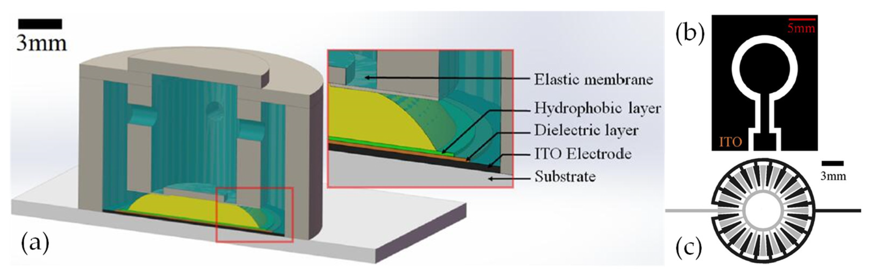
- Cheng, Y.; Chen, C.; Cao, J.; Bao, C.; Yang, A.; Hao, Q. Tunable Lens Using Dielectric Elastomer Sandwiched by Transparent Conductive Liquid. Opt. Lett. 2021, 46, 4430. [Google Scholar] [CrossRef]
- Wang, L.; Hayakawa, T.; Ishikawa, M. Dielectric-Elastomer-Based Fabrication Method for Varifocal Microlens Array. Opt. Express 2017, 25, 31708–31717. [Google Scholar] [CrossRef]
- Zhang, C.; He, H.; Li, Y.; Sun, Y.; Dong, Z. Modeling and Design of Dielectric Elastomer Actuated Tunable Lens with Dual Chambers. AIP Adv. 2022, 12, 075119. [Google Scholar] [CrossRef]
- Liu, S.; Qiu, Y.; Yu, W. Self-Contained Focus-Tunable Lenses Based on Transparent and Conductive Gels. Macromol. Mater. Eng. 2020, 305, 2000393. [Google Scholar] [CrossRef]
- Cheng, Y.; Li, Z.; Chen, C.; Cao, J.; Bao, C.; Ning, Y.; Hao, Q. Varifocal Liquid Lens Driven by a Conical Dielectric Elastomer Actuator. Appl. Opt. 2022, 61, 4633. [Google Scholar] [CrossRef] [PubMed]
- Xu, M.; Xu, D.; Ren, H.; Yoo, I.-S.; Wang, Q.-H. An Adaptive Liquid Lens with Radial Interdigitated Electrode. J. Opt. 2014, 16, 105601. [Google Scholar] [CrossRef] [Green Version]
- Xu, M.; Wang, X.; Ren, H. Tunable Focus Liquid Lens with Radial-Patterned Electrode. Micromachines 2015, 6, 1157–1165. [Google Scholar] [CrossRef] [Green Version]
- Mishra, K.; Narayanan, A.; Mugele, F. Design and Wavefront Characterization of an Electrically Tunable Aspherical Optofluidic Lens. Opt. Express 2019, 27, 17601. [Google Scholar] [CrossRef] [PubMed]
- Park, I.S.; Park, Y.; Oh, S.H.; Yang, J.W.; Chung, S.K. Multifunctional Liquid Lens for Variable Focus and Zoom. Sens. Actuators A Phys. 2018, 273, 317–323. [Google Scholar] [CrossRef]
- Lee, J.; Park, Y.; Oh, S.H.; Chung, S.K. Multifunctional Liquid Lens (MLL) for Variable Focus and Variable Aperture. In Proceedings of the 2017 IEEE 30th International Conference on Micro Electro Mechanical Systems (MEMS), Las Vegas, NV, USA, 22–26 January 2017; IEEE: Las Vegas, NV, USA, 2017; pp. 781–784. [Google Scholar]
- Xu, J.; Zhao, Y.; Liu, C.; Wang, Q. Non-Aqueous Organic Solution Based on a Large-Aperture Spherical Electrowetting Liquid Lens with a Wide Tunable Focal Length Range. J. Mater. Chem. C 2022, 10, 6778–6793. [Google Scholar] [CrossRef]
- Liu, C.; Wang, D.; Wang, Q.-H.; **ng, Y. Multifunctional Optofluidic Lens with Beam Steering. Opt. Express 2020, 28, 7734. [Google Scholar] [CrossRef]
- Park, J.; Ha, J.; Choi, K.; Bae, J.; Kim, H.-Y. Critical AC Frequency for Stable Operation of Electrowetting-Driven Optofluidic Devices with Polymeric Electrolyte Solutions. J. Mech. Sci. Technol. 2019, 33, 1793–1797. [Google Scholar] [CrossRef]
- Chen, Q.; Li, T.; Zhu, Y.; Yu, W.; Zhang, X. Dielectrophoresis-Actuated in-Plane Optofluidic Lens with Tunability of Focal Length from Negative to Positive. Opt. Express 2018, 26, 6532. [Google Scholar] [CrossRef]
- Chen, Q.; Li, T.; Li, Z.; Lu, C.; Zhang, X. Dielectrophoresis-Actuated Liquid Lenses with Dual Air/Liquid Interfaces Tuned from Biconcave to Biconvex. Lab Chip 2018, 18, 3849–3854. [Google Scholar] [CrossRef]
- Chen, Q.; Tong, X.; Zhu, Y.; Tsoi, C.C.; Jia, Y.; Li, Z.; Zhang, X. Aberration-Free Aspherical in-Plane Tunable Liquid Lenses by Regulating Local Curvatures. Lab Chip 2020, 20, 995–1001. [Google Scholar] [CrossRef] [PubMed]
- Shian, S.; Diebold, R.M.; Clarke, D.R. Tunable Lenses Using Transparent Dielectric Elastomer Actuators. Opt. Express 2013, 21, 8669–8676. [Google Scholar] [CrossRef] [PubMed]
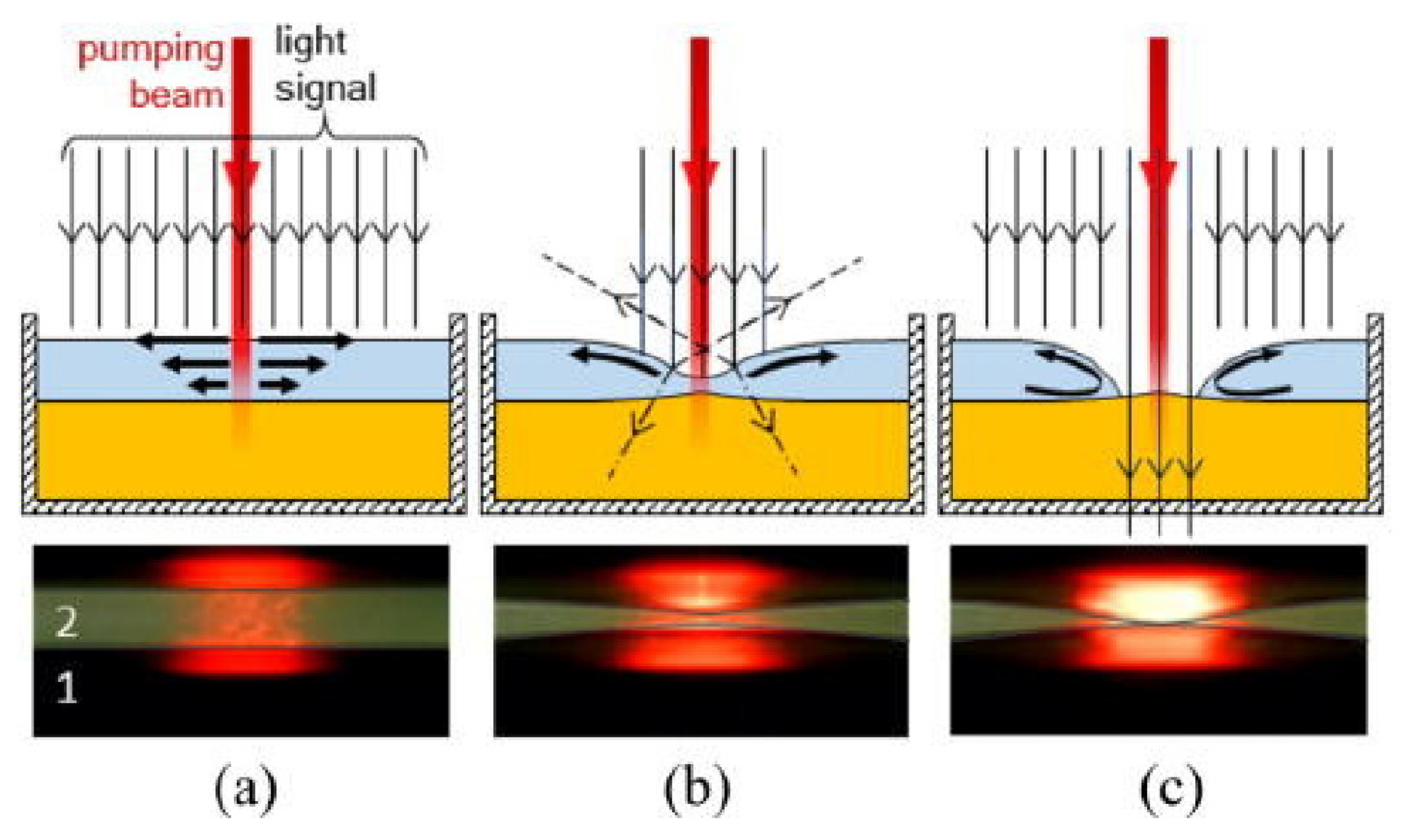
- Malyuk, A.Y.; Ivanova, N.A. Varifocal Liquid Lens Actuated by Laser-Induced Thermal Marangoni Forces. Appl. Phys. Lett. 2018, 112, 103701. [Google Scholar] [CrossRef]
- Malyuk, A.Y.; Ivanova, N.A. Optofluidic Lens Actuated by Laser-Induced Solutocapillary Forces. Opt. Commun. 2017, 392, 123–127. [Google Scholar] [CrossRef]
- Zhao, H.; Yang, Y.; Chin, L.; Chen, H.; Zhu, W.; Zhang, J.; Yap, P.; Liedberg, B.; Wang, K.; Wang, G.; et al. Optofluidic Lens with Low Spherical and Low Field Curvature Aberrations. Lab Chip 2016, 16, 1617–1624. [Google Scholar] [CrossRef] [PubMed] [Green Version]
- Chen, Q.; Jian, A.; Li, Z.; Zhang, X. Optofluidic Tunable Lenses Using Laser-Induced Thermal Gradient. Lab Chip 2016, 16, 104–111. [Google Scholar] [CrossRef] [PubMed]
- Liu, H.; Shi, Y.; Liang, L.; Li, L.; Guo, S.; Yin, L.; Yang, Y. A Liquid Thermal Gradient Refractive Index Lens and Using It to Trap Single Living Cell in Flowing Environments. Lab Chip 2017, 17, 1280–1286. [Google Scholar] [CrossRef]
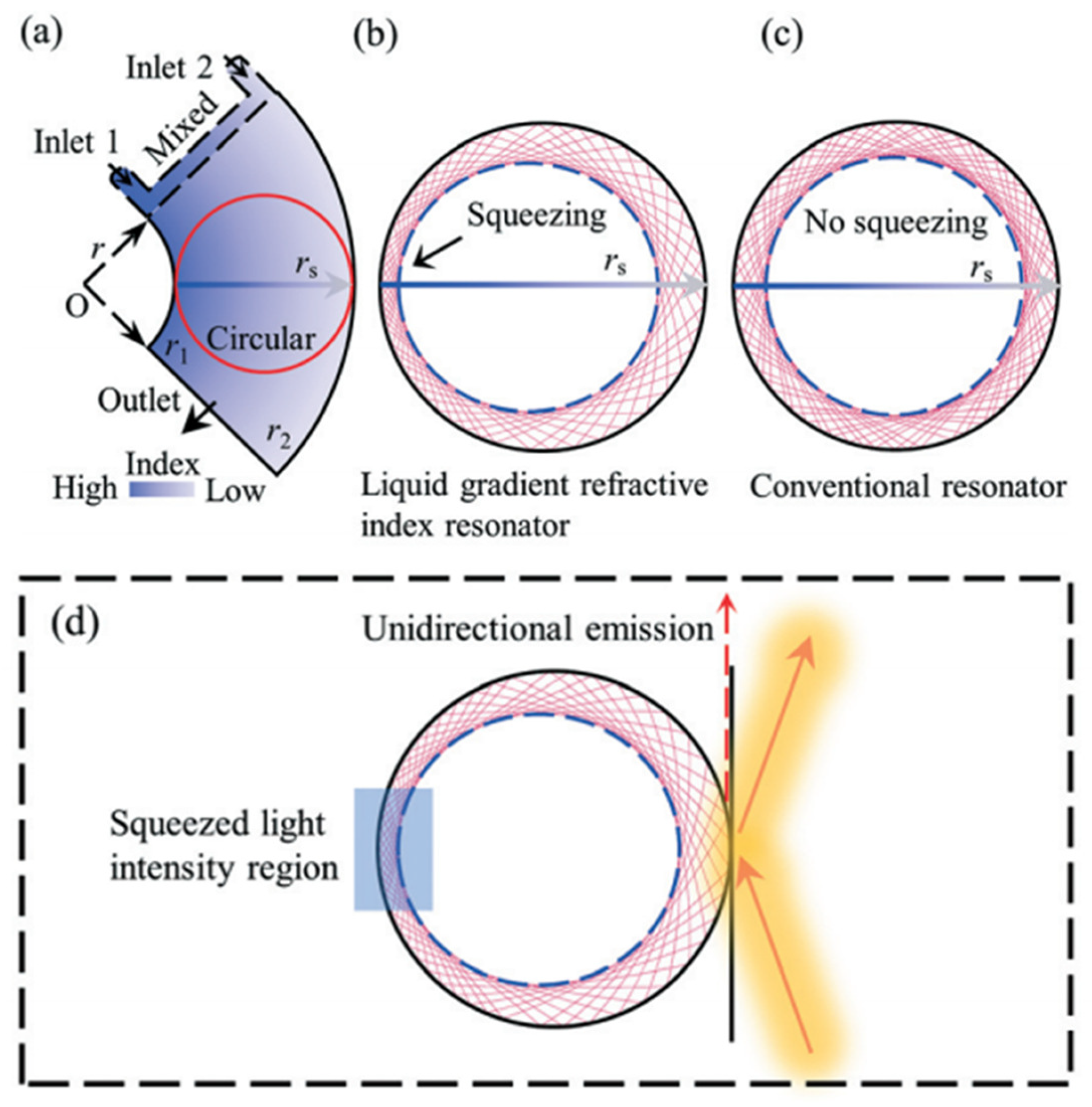
- Liu, H.L.; Zuo, Y.F.; Zhu, X.Q.; Yang, Y. Optofluidic Gradient Refractive Index Resonators Using Liquid Diffusion for Tunable Unidirectional Emission. Lab Chip 2020, 20, 2656–2662. [Google Scholar] [CrossRef]
- Klyuev, D.S.; Fliagin, V.M.; Al-Muzaiqer, M.; Ivanova, N.A. Laser-Actuated Optofluidic Diaphragm Capable of Optical Signal Tracking. Appl. Phys. Lett. 2019, 114, 011602. [Google Scholar] [CrossRef]
- Wan, J.; Xue, F.; Liu, C.; Huang, S.; Fan, S.; Hu, F. Optofluidic Variable Optical Attenuator Controlled by Electricity. Appl. Opt. 2018, 57, 8114. [Google Scholar] [CrossRef]
- Xu, P.; Wan, J.; Zhang, S.; Duan, Y.; Chen, B.; Zhang, S. 2 × 2 Optofluidic Switch Chip with an Air Shutter. Appl. Opt. 2019, 58, 4637. [Google Scholar] [CrossRef] [PubMed]
- Liang, Z.; Ding, W.; Zhao, R.; Huang, Y.; Kong, M.; Chen, T. Design and Characteristics of an Optofluidic Phase Modulator Based on Dielectrowetting. Langmuir 2021, 37, 769–773. [Google Scholar] [CrossRef] [PubMed]
- Huang, Y.; Zhao, R.; Liang, Z.; Zhang, Y.; Kong, M.; Chen, T. Dielectrowetting Actuation of Droplet: Theory and Experimental Validation. Chin. Phys. B 2021, 30, 106801. [Google Scholar] [CrossRef]


| Device Type | Classification | Working Principle | Materials |
|---|---|---|---|
| Adaptive LC lens | Modal type | Electronically | NLC [47] |
| Pattern type | NLC [56] | ||
| Tunable LC filter/absorbers | Visible to infrared | Electronically | SPLC [71], CLC [70], NLC [68] |
| THz | NLC [73,80], PDLC [77] | ||
| LC Beam controllers | Deflector | Electronically | CLC [84], NLC [29,89] |
| Laser polarization | Light-operated | NLC [100] | |
| Optical switch | Electronically | NLC [93] | |
| Bistable state LC devices | E-paper | Electronically | PDLC [103], TNLC [106], CLC [107] |
| Smart windows | Electronically, light-operated | PDLC [114], CLC [109], PSLC [108] |
| Device Type | Working Principle | Device Type | Materials |
|---|---|---|---|
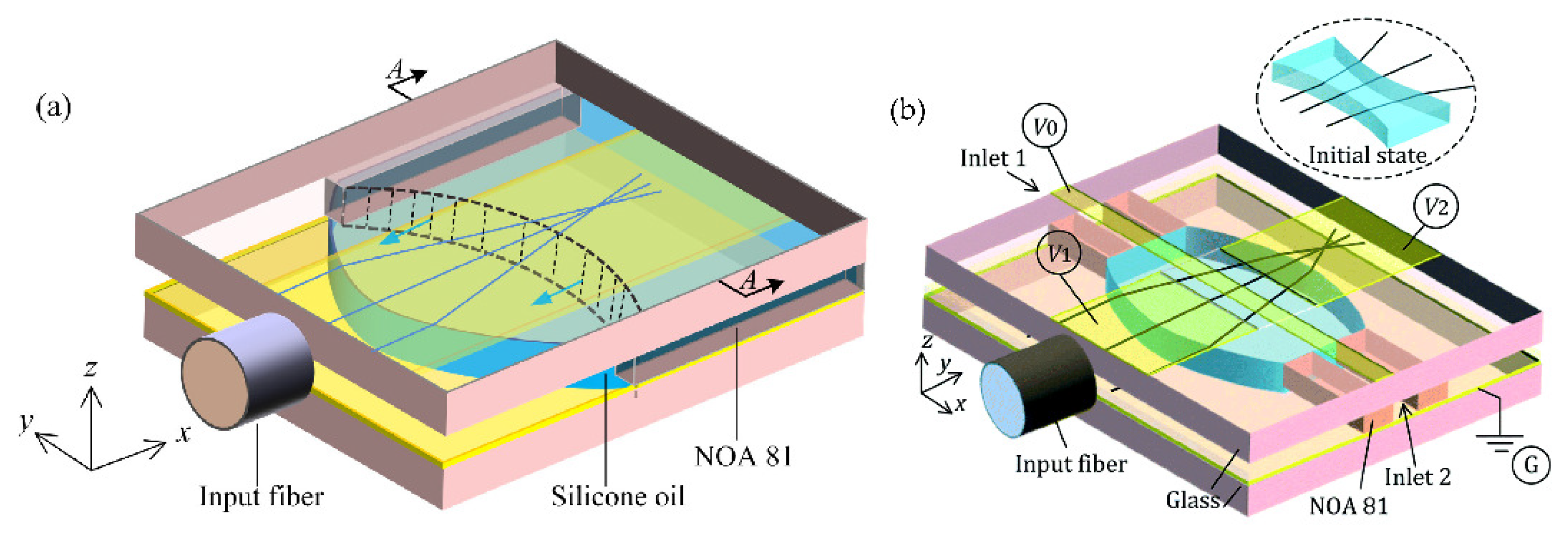
| Interface modulation | EW | Tunable lens, deflector | Silicone oil [126] |
| DEP | Tunable lens, e-paper | Silicone oil [129,130] | |
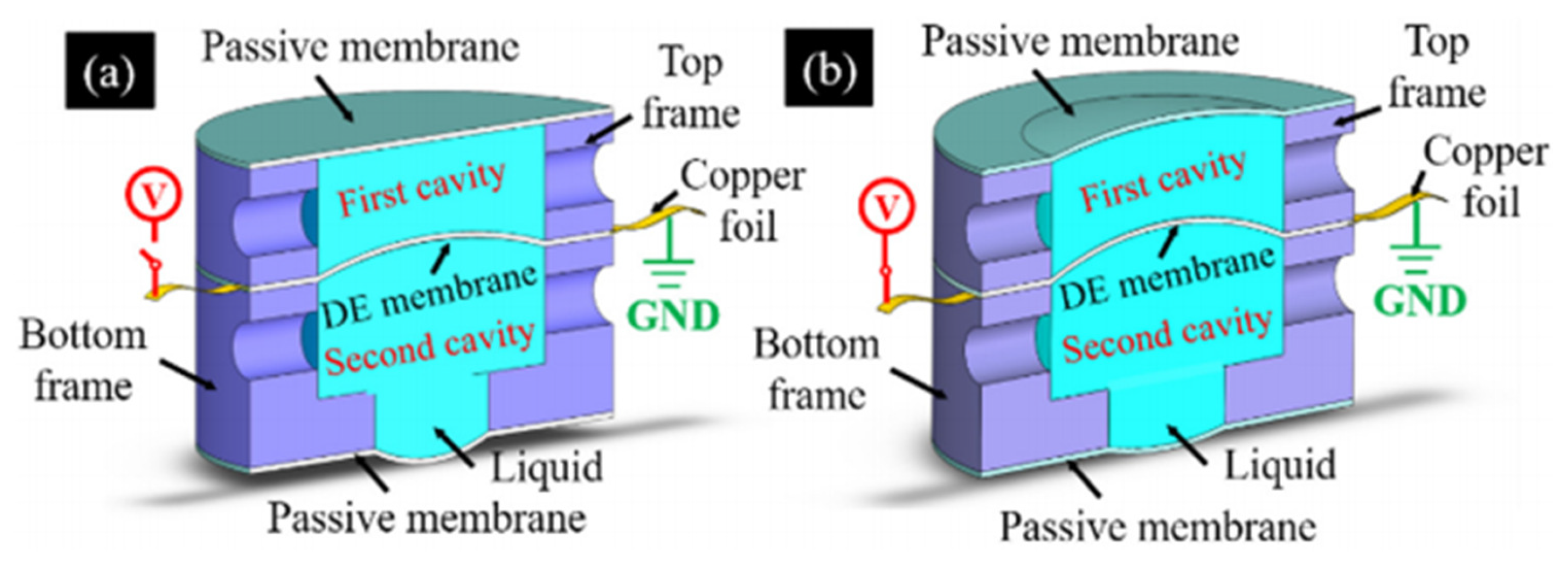
| DE membranes | Tunable lens | Glycerol [118] | |
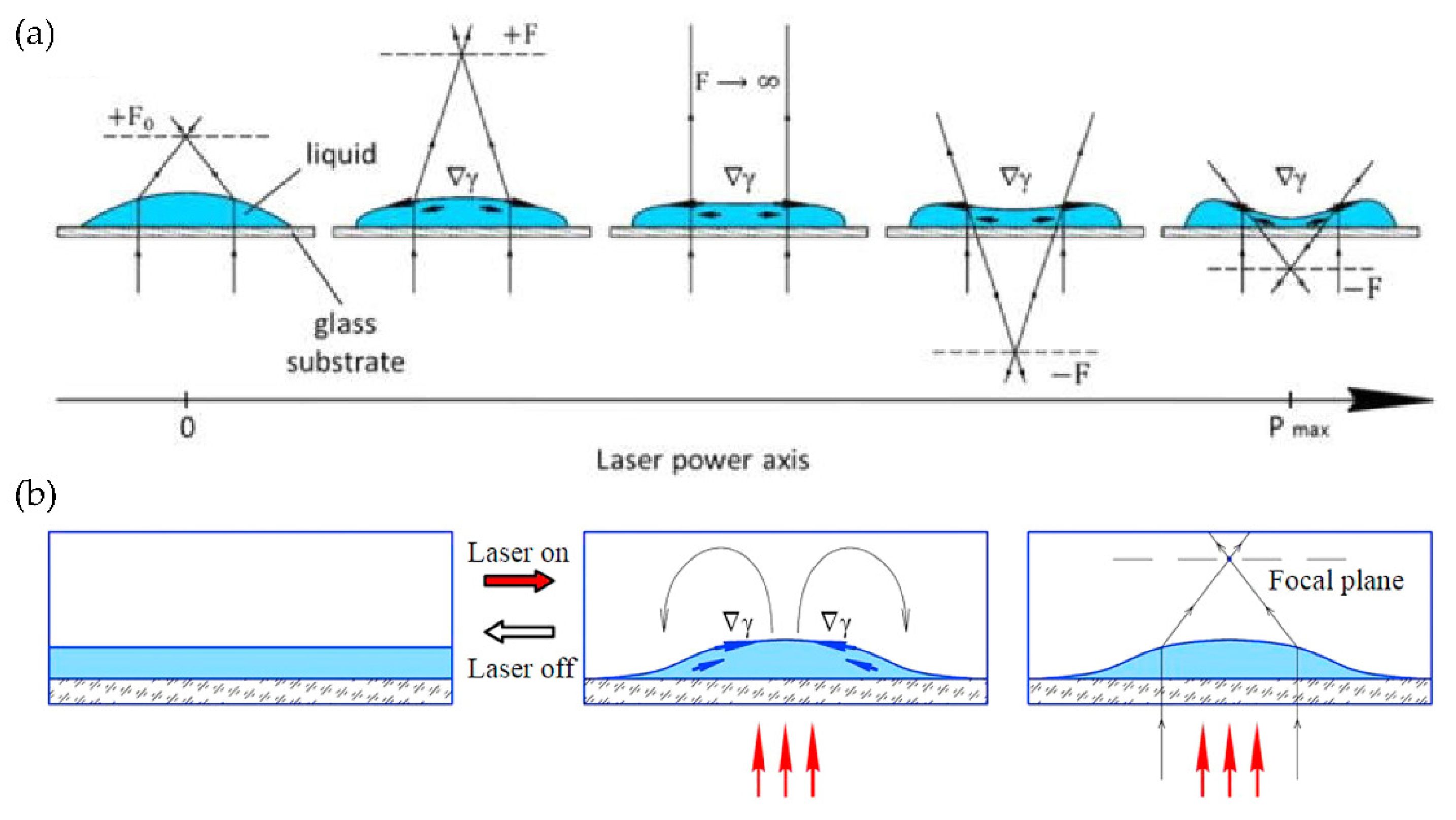
| Thermal | Tunable lens, beam tracker | Ethanol and glycol [133,134] | |
| Index distribution | Diffusion | GRIN lens | Benzyl alcohol [136] |
| GRIN resonator | Benzyl alcohol and glycol [138] | ||
| Bending waveguide | Glycol [43] |
Publisher’s Note: MDPI stays neutral with regard to jurisdictional claims in published maps and institutional affiliations. |
© 2022 by the authors. Licensee MDPI, Basel, Switzerland. This article is an open access article distributed under the terms and conditions of the Creative Commons Attribution (CC BY) license (https://creativecommons.org/licenses/by/4.0/).
Share and Cite
Wu, Q.; Zhang, H.; Jia, D.; Liu, T. Recent Development of Tunable Optical Devices Based on Liquid. Molecules 2022, 27, 8025. https://doi.org/10.3390/molecules27228025
Wu Q, Zhang H, Jia D, Liu T. Recent Development of Tunable Optical Devices Based on Liquid. Molecules. 2022; 27(22):8025. https://doi.org/10.3390/molecules27228025
Chicago/Turabian StyleWu, Qi, Hongxia Zhang, Dagong Jia, and Tiegen Liu. 2022. "Recent Development of Tunable Optical Devices Based on Liquid" Molecules 27, no. 22: 8025. https://doi.org/10.3390/molecules27228025