7.1. Experimental Database
The database used in this paper is explained in
Table 2. The database was collected within about a 42 km range from the Seoul toll gate to the Hobeop junction of Yeongdong highway in South Korea. In
Table 2, DB 1 is used only to train the VJ corner detector, and DB 2 is used for all training phases including the VJ corner detector, corner HV, road sign HV, and the statistics of road sign HG. DB 3 is used to evaluate each algorithm step. All three DBs were collected by the same camera but the type of vehicle used for collection in DB 1 is different to that in collecting DB 2 and DB 3. DB 2 and DB 3 were collected from different direction lanes of the expressway. The different direction lanes in the expressway are divided by a central reservation and they may be considered as different roads. The image resolution is 1280
1024.
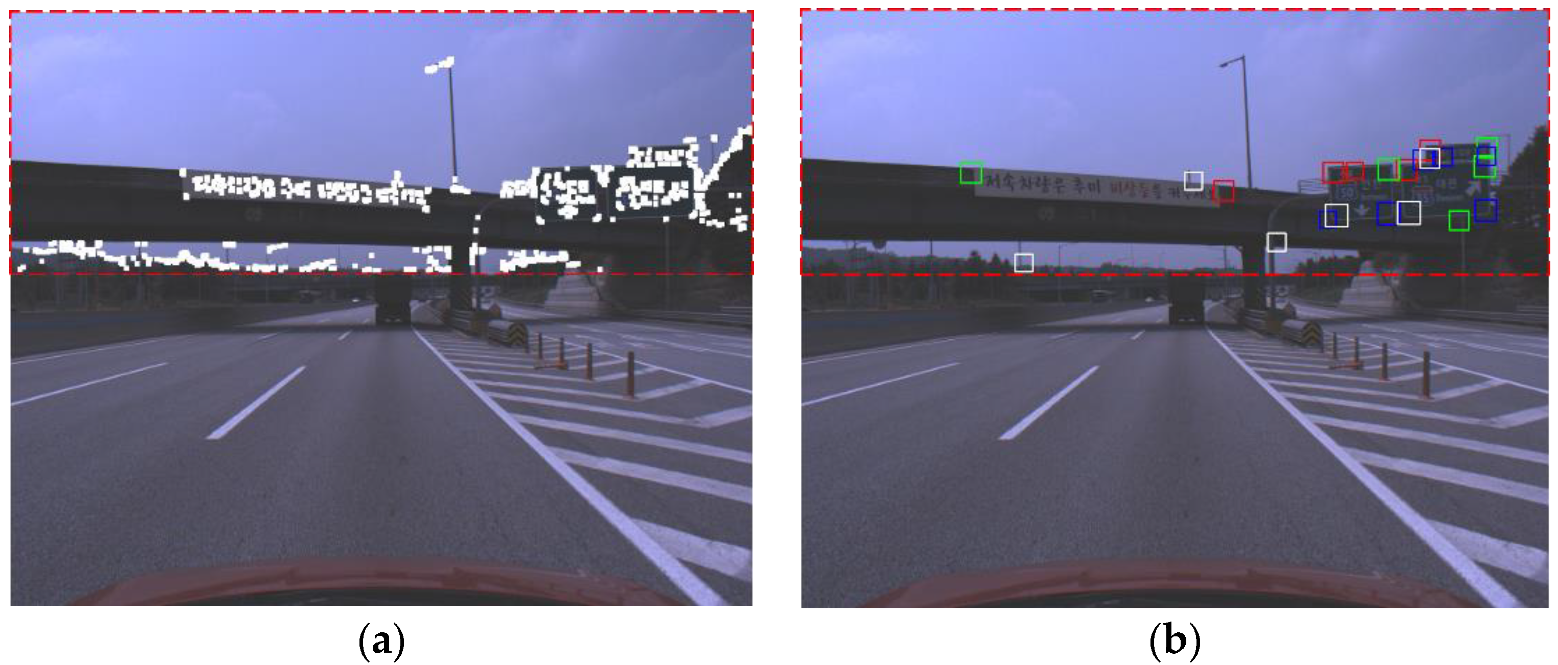
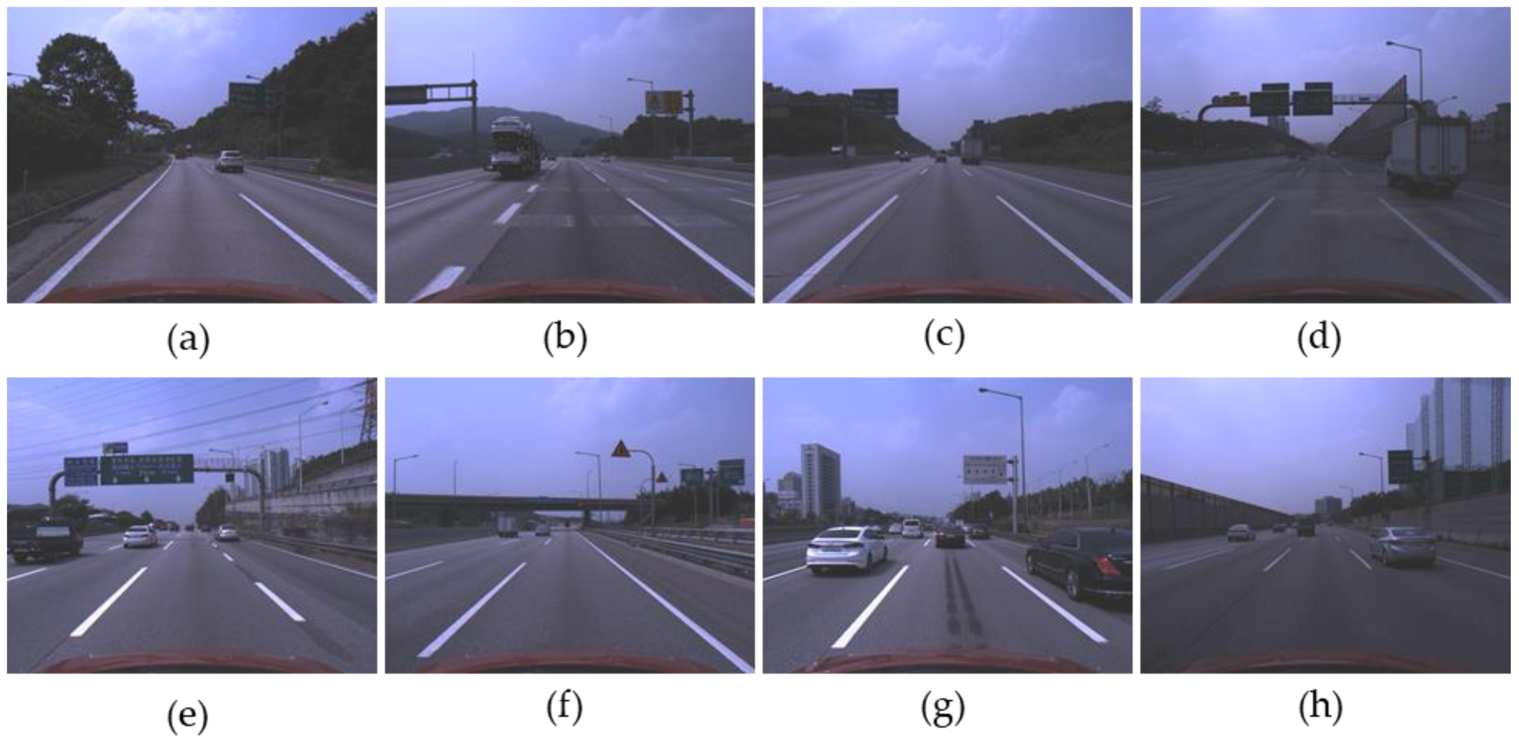
Figure 11 shows sample images in the experimental database.
The experimental database includes the various kinds of road sign and various backgrounds such as forests, bridges, and soundproofing walls.
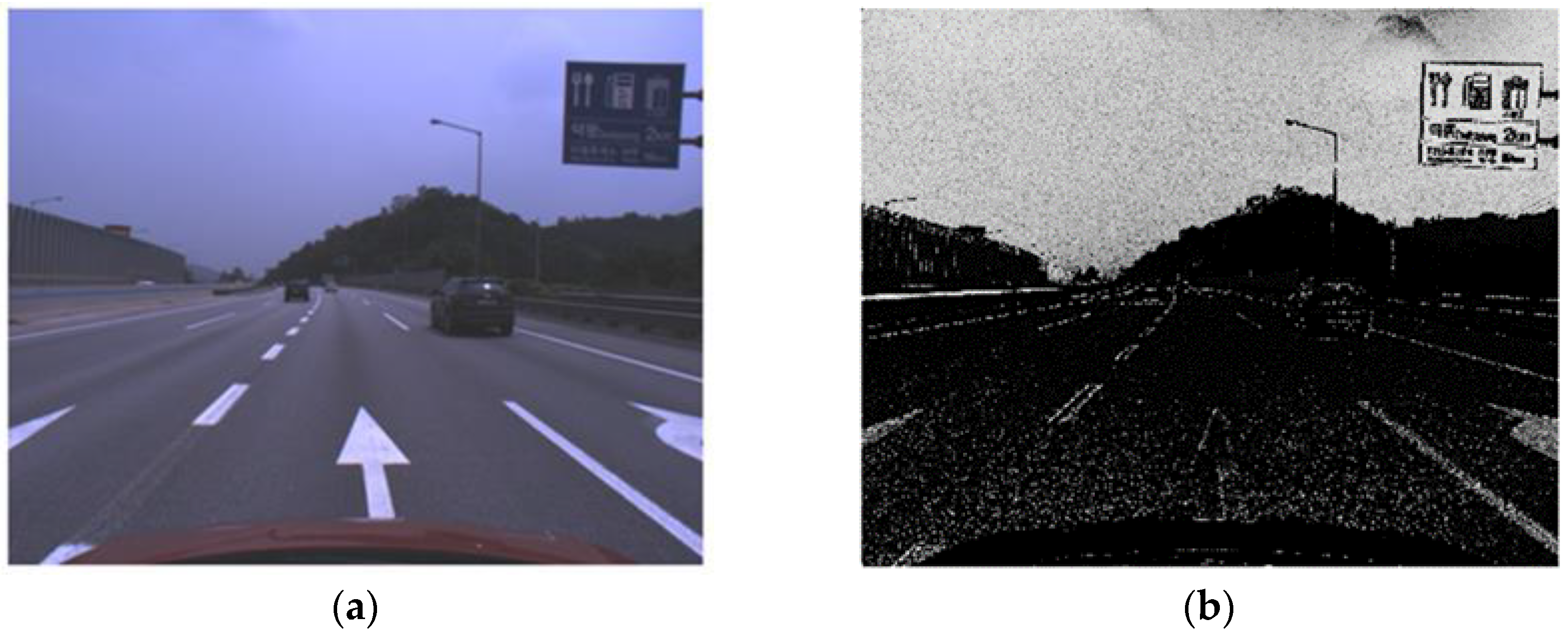
Figure 11a,c show the case that the contrast between a road sign and background is very low.
Figure 11b shows the road sign whose background is painted by two colors.
Figure 11f shows the road sign far from an ego-vehicle.
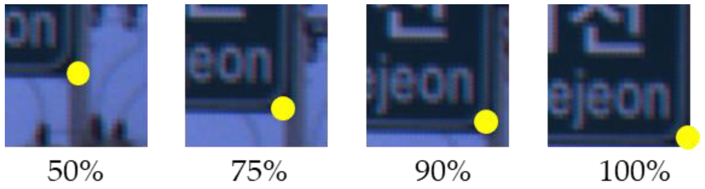
Figure 11e,h show the road signs with various aspect ratios. We define the maximum detection distance as 30 m. For evaluation, we assume the installation height of a road sign as 5 m and select the images including the road signs whose estimated distances from an ego-vehicle are within 30 m.
7.2. Experimental Results
As shown in
Table 3, we compare three methods: the proposed method without the FAST corner ROI, the proposed method with the FAST corner ROI, and YOLOv3 using the convolutional neural network (CNN) [
36]. The proposed method is one of the part-based approaches but YOLOv3 is trained to detect a whole body of a road sign at once and is one of the appearance-based approaches. Therefore, YOLOv3 does not have several intermediate steps unlike the proposed method, and only its final performance is described in
Table 3. The H/W spec for the experiment follows as: CPU (
[email protected]), OS (windows 10), and RAM (16 GB). The method without the FAST corner ROI sets the upper part of an image whose vertical coordinate is under 450 as the ROI for the corner HG. In
Table 3, the corner HG processing time of the proposed method is the summation time of the corner ROI setup and the corner HG. In the corner HG, the VJ detector is our modified version of the OpenCV library to operate in a single thread [
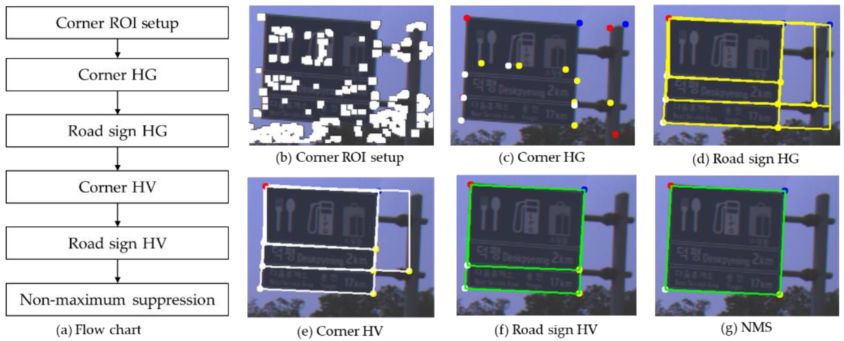
46]. In order to evaluate the corner detection performance, if the distance between a corner ground truth (GT) and a detected corner is less than 10 pixels, the detected corner is considered as a true positive (TP) and otherwise as a false positive (FP). In the case of a road sign, if the IOU between a detected road sign and a road sign GT is over 0.5, the detected road sign is considered as a TP and otherwise as a FP. The recall and the precision for the corner level are evaluated only in the corner HG step and the performances in the other steps are evaluated for the road sign level.
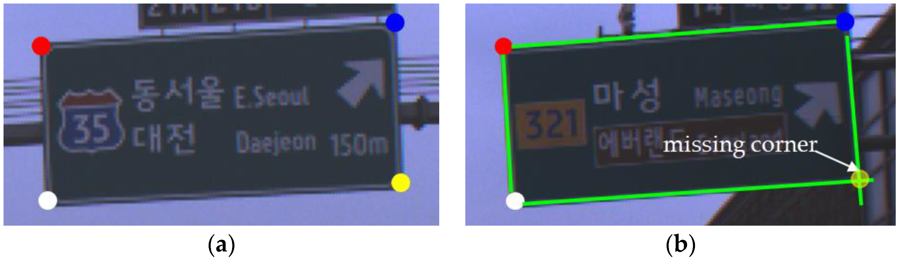
In the corner HG step, it is important to keep the recall of road sign corners high. In the case of using the FAST corner ROI, while the recall is rarely degraded, the processing time is reduced drastically. The experimental results show that the proposed method can reduce the processing time of the corner HG up to four times by using the FAST corner ROI. The recall in the sign HG step is slightly improved because the road sign hypothesis with one missing corner can be also generated through the parallelogram relation. Furthermore, the low precision in the corner HG indicates that there are a lot of falsely detected corners. Nevertheless, the sign HG which takes just 2.5 ms significantly improves the precision and this shows that a lot of falsely detected corners can be effectively removed through geometric constraints. The precision improvement by the corner HV is small but the improvement by the sign HV is large. This indicates that even if there are few false corners, there may be a lot of false corner combinations that satisfy the geometric constraints. The final performance after passing the sign NMS step shows greater improved precision and this indicates that a lot of road sign hypotheses overlap.
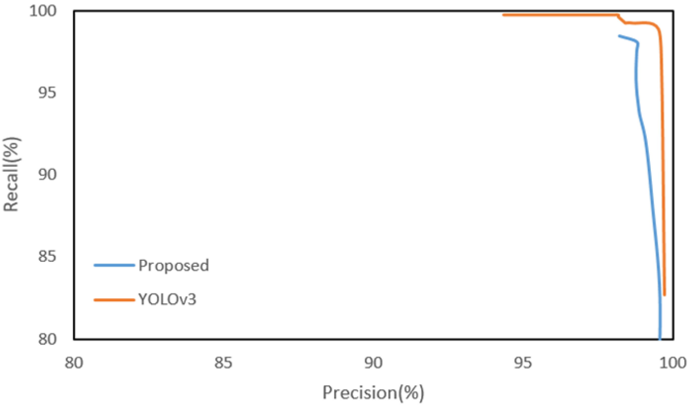
The final road sign recall of the proposed method is 97.48% or about 2% lower than YOLOv3, but the precision is 98.78%, which is better than YOLOv3.
Figure 12 shows the recall-precision curves of the proposed method and YOLOv3. The curve of the proposed method is generated by adjusting only the SVM threshold of the road sign HV. Since some of the true corners may be missed in the steps prior to the road sign HV, the recall of the proposed method cannot reach 100% by adjusting only the SVM threshold. Although the detection performance of the proposed method is slightly lower than YOLOv3, the proposed method may be more effective than YOLOv3 in a vehicle localization system when considering real time processing. The proposed method takes a total of about 66.7 ms and can process 15 frames per second. However, YOLOv3 takes a total of about 4802 ms on the CPU even if the input image resolution is reduced to a quarter (640 × 512). Yet, the processing time for all three methods can be significantly reduced through a high-performance parallel processing H/W like the GPU, but the price and operating conditions of the GPU have not yet met the requirements of a vehicle.
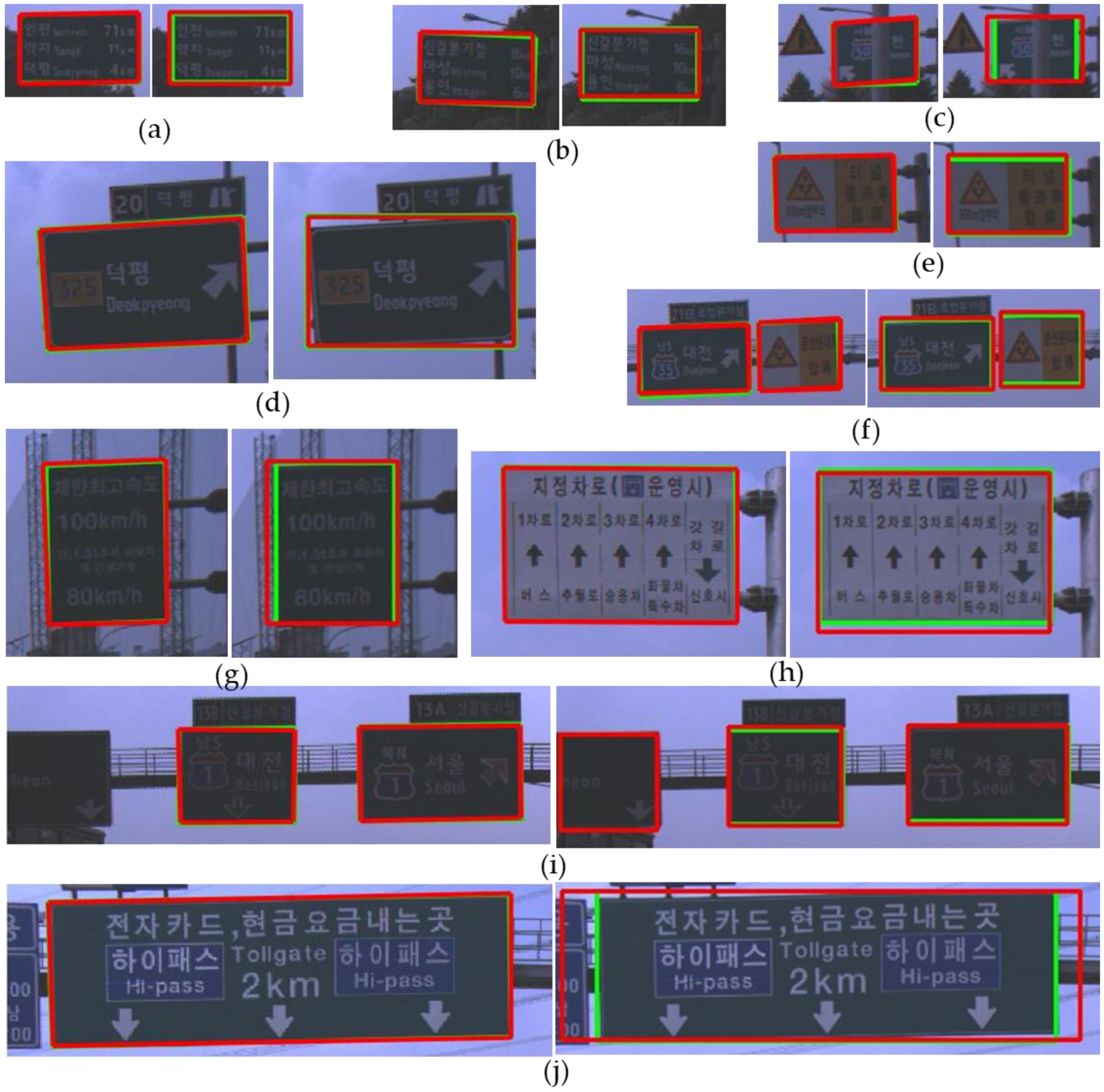
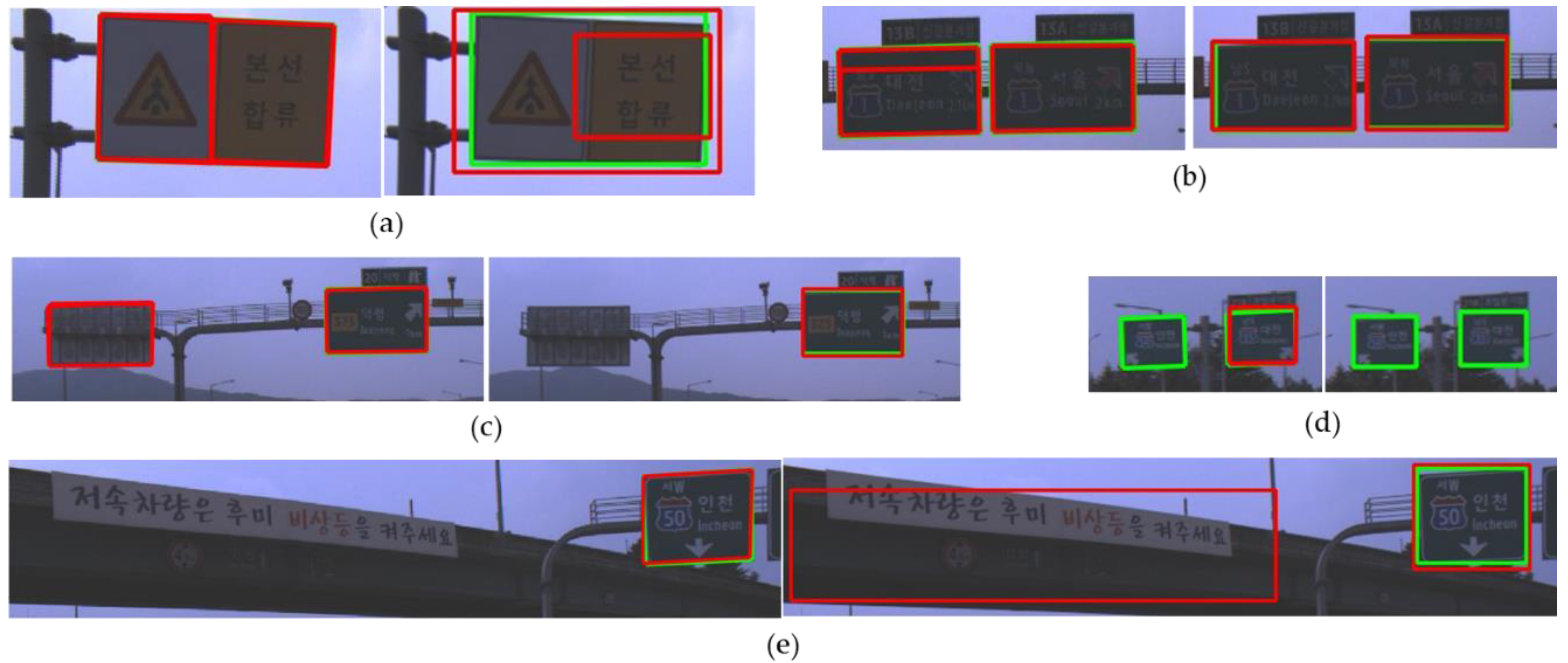
Figure 13 shows good detection results of both the proposed method and YOLOv3. In
Figure 13, a red box depicts a detection result and a green box depicts a ground truth. In the sub-figures of
Figure 13, the left side is the result of the proposed method and the right side is the result of YOLOv3. Even in cases that the contrast between a road sign and background is too low to find the boundary clearly between them as shown in
Figure 13a,b, both the proposed method and YOLO v3 detect a road sign successfully.
Figure 13c shows that both methods can detect a partially occluded road sign. Although YOLOv3 adopts an appearance-based approach, this extracts many complicated features through deep CNN and can detect a partially occluded road sign. On the other hand, the proposed method uses relatively simple hand-craft features. However, due to the adoption of the part-based approach, the proposed method can detect also a partially occluded road sign if more than three corners of the road sign are detected. As shown in
Figure 13d, the proposed method can find the boundary of the rotated road sign more accurately than YOLOv3 because the proposed method detects the corners of the sign. In the localization system, it is important to accurately detect the image points corresponding to the reference points of a road sign stored in the map. In this view point, the part-based approach such as the proposed method is more advantageous than the appearance-based approach.
Figure 13e,f show that both methods detect a road sign whose background is divided into two regions. However,
Figure 14a shows that this kind of a road sign may be sometimes detected as two separate ones by both methods.
Figure 13g–j show that road signs whose aspect ratios and kinds are different can be detected well by both methods.
Figure 14 shows examples where there is an error in at least one of the detection results of both methods. The proposed method detects incorrectly one road sign as two separate ones which is shown in
Figure 14a. However, this error can be solved by applying the NMS between different corner types.
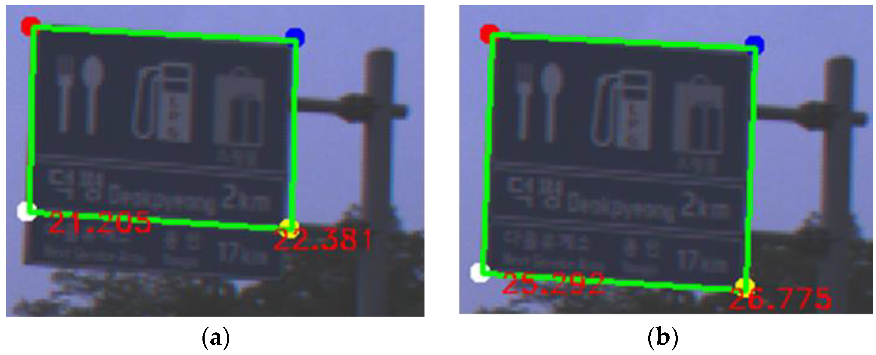
Figure 14b shows an example that the proposed method fails to integrate the overlapped road sign hypotheses correctly because of the tight conditions of the road sign NMS. The proposed method is based on the part-based approach and the method does not utilize the inside patterns on a road sign as detection features. As a result, the proposed method can unintentionally detect a road sign not facing an ego-vehicle, which is shown in
Figure 14c. However, YOLOv3 can filter out these unintended detections by utilizing the inside patterns of the sign. On the other hand, this utilization of the inside patterns causes the side effect that the letter patterns on the background can be falsely detected as a road sign, which is shown in
Figure 14e.
Figure 14d shows the detection failures of road signs far from an ego-vehicle. Only the proposed method detected one of two road signs in the far distance. Yet, if the processing time is no matter, YOLOv3 may detect the road signs in the far distance by increasing the input image resolution.


