2.1. Theoretical Analysis
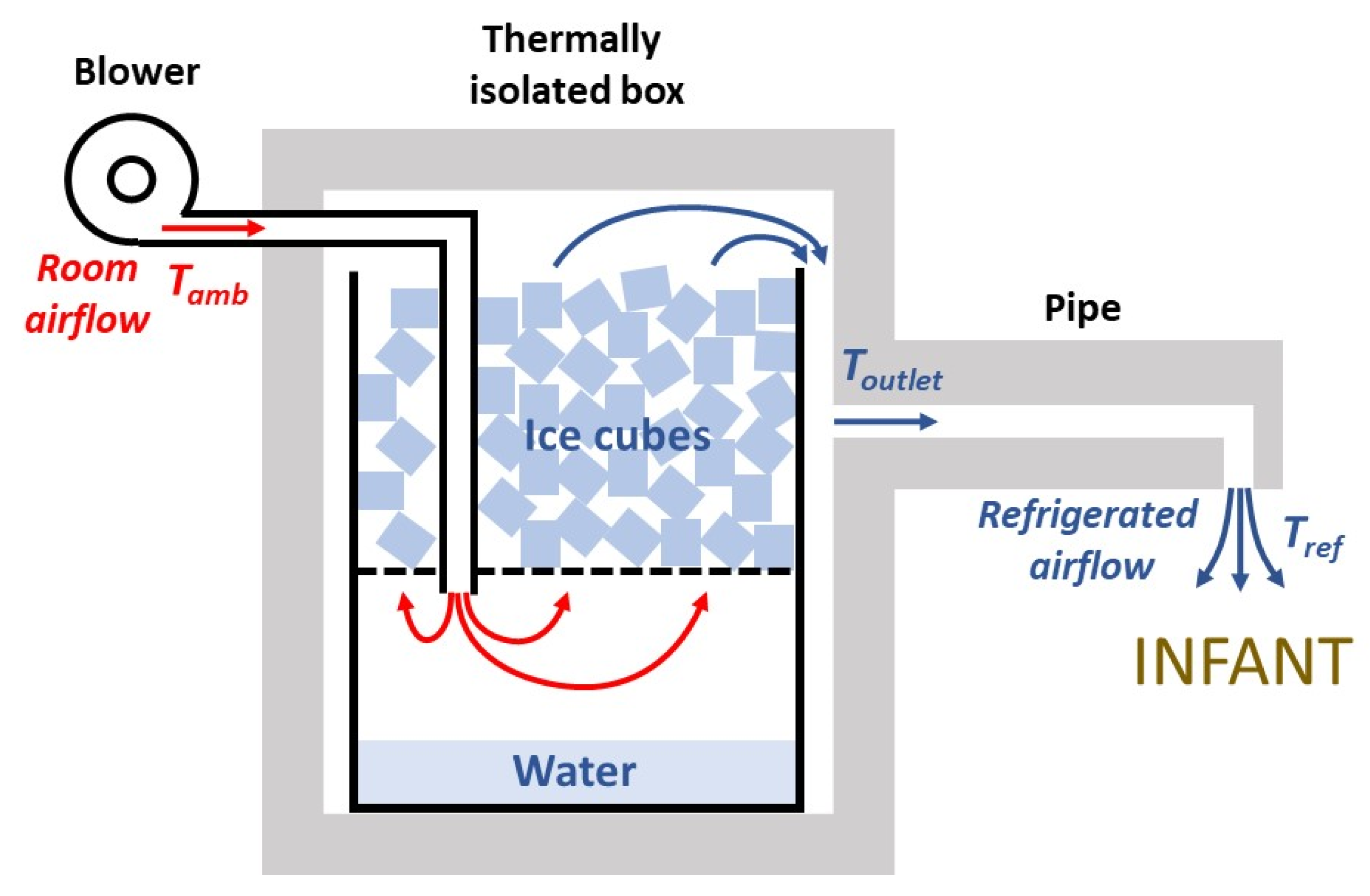
Figure 1 shows a diagram of the designed generator of refrigerated air. An airflow of room air is introduced by a blower, and is refrigerated by passing it through ice cubes, then leaving the setting through an outlet pipe placed on top of the infant. To minimize wasting of the ice refrigeration capacity, the setting is enclosed in a thermally isolated box. First, a theoretical model was delineated to assess whether the assembly in
Figure 1 can feasibly provide sufficient refrigeration power. The negative heat transfer from ice thawing is spent on three processes: cooling of the airflow, heat transfer through the chamber walls, and condensation of water vapor from the airflow.
2.1.1. Air Cooling Process in the Chamber
When the average temperature inside the chamber (
Tchamber) (
Figure 1) is lower than the ambient temperature (
Tamb), the heat transfer rate (
Q’wall) into the chamber through the walls having thickness
d, total surface
A, and made of a material with thermal conductivity
Kwall, is
The negative heat transfer rate (
Q’air) to an airflow
V’ of density
ρ (1.2 g·L
−1) and specific heat capacity
c (1 J·g
−1·K
−1) when its temperature is reduced from
Tamb to
Toutlet is
The mass (
m) of water vapor contained in a volume
V of air at
T and
RH is
where
Wtmol is the water molecular weight (18 g·mol
−1),
R is the gas constant (8.31 J·K
−1·mol
−1), and
PH2O(
T) is the saturated water vapor pressure at
T [
24]. When an airflow
V’ at
Tamb and
RHamb is refrigerated to
Toutlet and is water vapor saturated (
RHoutlet = 100%)
, water vapor will be condensed if the difference between the air content of water vapor before and after refrigeration is positive. In that case, considering that the latent heat of water vaporization is
Cv (2424 J·g
−1), the rate of heat required for water condensation for an airflow
V’, is
Hence, the total heat transfer rate to the ice, which causes its thawing, is
Given the latent heat of ice fusion
Cf (334 J·g
−1), the ice thawing rate R corresponding to a heat transfer
Q’ is
For instance, in the case of very hot and dry desert conditions, such as Tamb = 45 °C, RHamb = 20%, if the chamber is cubic with lateral length 25 cm (A = 0.375 m2), d = 4 cm, the wall material is expanded polystyrene (K = 0.035 W·K−1·m−1), Tchamber = 5 °C, Toutlet = 15 °C, and airflow is V’ = 0.5 L·s−1, then Q’wall = 13.1 W, Q’air = 18.0 W, Q’con = 0.3 W, and thus Q’ = 31.4 W). Accordingly, the rate of ice thawing would be R = 0.339 kg·h−1, and an initial ice load of 1.5 kg into the chamber would last for 4.4 h. For the same assembly, in the case of typical hot and humid tropical conditions of Tamb = 35 °C, RHamb = 60%, then Q’wall = 9.8 W, Q’air = 12.0 W, Q’con =13.2 W, indicating that the heat rate corresponding to water vapor condensation would be considerably increased. As, in this case, Q’ = 35.1 W, the rate of ice thawing would be R = 0.378 kg·h−1, and an initial ice load of 1.5 kg into the chamber would last for 4.0 h. Theoretically, these ice lasting times (4.4 and 4.0 h) would be slightly longer because the negative heat transfer corresponding to heating the ice in the chamber (from ≈−15 °C when obtained from a domestic freezer) is ignored.
2.1.2. Air Heating Process in the Pipe
The airflow leaving the isolated box at
Toutlet should be conducted close to the infant by a pipe (
Figure 1). Because of heat transfer through the pipe walls, the airflow will be heated to the final temperature of the refrigerated air leaving the device (
Tref). The wall heat transfer in a constant-section pipe of length
L, a material wall with thermal conductivity
Kpipe, external temperature
Tamb and mean internal temperature (
Toutlet +
Tref)/2 is
where
C is a geometrical factor that depends on the section geometry of the pipe [
25]. Given that the pipe has a constant section, considering a uniform internal pipe temperature equal to (
Toutlet +
Tref)/2 is equivalent to accounting for the linear temperature decrease inside the pipe.
If the pipe is cylindrical with internal and external radii
ri and
re, respectively,
If the pipe has a square section with internal and external wall widths
wi and
we, respectively,
The heat rate to increase the airflow
V’ in the pipe from
Toutlet to
Tref is
Hence,
Tref can be derived by solving
Q’wall,pipe =
Q’wall,air, for
Tref ≤
Tamb:
where α = 2
π·
L·
Kpipe·
C, and
β =
V’·ρ·c.
Thus, adequate thermal isolation of the pipe is very important to minimize the amount of heating of the air flowing through the pipe. For instance, in case that Toutlet = 15 °C, Tamb = 45 °C, V’ = 0.5 L·s−1, and the pipe is a L = 20 cm long simple cylindrical plastic (PVC) tube (Kpipe = 0.2 W·K−1·m−1) with ri = 1 cm and re = 1.3 cm (i.e., 3 mm wall thickness), the final temperature of refrigerated air Tref would increase to Tref = 41.6 °C, very close to Tamb. By contrast, if the pipe is L = 20 cm long, having a square section, and its walls are made of 4 cm thick expanded polystyrene (Kpipe = 0.035 W·K−1·m−1) with widths wi = 1 cm and we = 9 cm, then the airflow in the pipe would be scarcely heated from Toutlet because Tref = 16.1 °C.
Therefore, the theoretical analysis of Equations (1)–(11) indicates that the approach is feasible for reasonable physical dimensions of the setting in the context of stressful thermal conditions.
2.3. Performance Assessment
The setting was tested under laboratory conditions inside a temperature- and humidity-controlled customized climatic chamber (61 × 63 × 83 cm) to mimic real-life thermal stress. Air temperature and relative humidity were continuously measured by a sensor (SHTC3, DollaTek, Hong Kong) and were Arduino-controlled using a heating ventilator (PTC Heater 100 W, 12 V; Fdit, Shenzhen, China) and a humidity nebulizer (Ultra-Neb 2000, Devilbiss, Mannheim, Germany). Airflow V’ was assessed by measuring pressure at the blower outlet with a transducer (DCXL01DS, Honeywell, Charlotte, NC, USA) and using the previously calibrated pressure–flow relationship of the blower for each driving voltage. The temperature of the refrigerated air (Tref) at the output of the device and at different distances from the output orifice was measured with a microthermistor (Micro-BetaChip, TE Connectivity, Escafusa, Switzerland). V’ and Tref signals were sampled and stored for subsequent analysis.
An infant manikin (modified from model 2390686, CGTrader, Vilnius, Lithuania) having dimensions corresponding to a ≈6 kg infant was 3D printed (S5, Ultimaker, Utrecht, The Nederland) using polylactic acid (PLA), and finally painted with a layer of brown liquid silicone. Once the refrigerated air source and the infant manikin were at thermal equilibrium within the climatic chamber, 1.7 kg of ice from a domestic freezer was loaded into the device, and the blower was switched on. The temperature at the manikin surface was assessed by a 220 × 160 infrared resolution thermal imaging camera (HT-18, Hti-** the infant to maintain normothermia. The small fluctuations observed in each
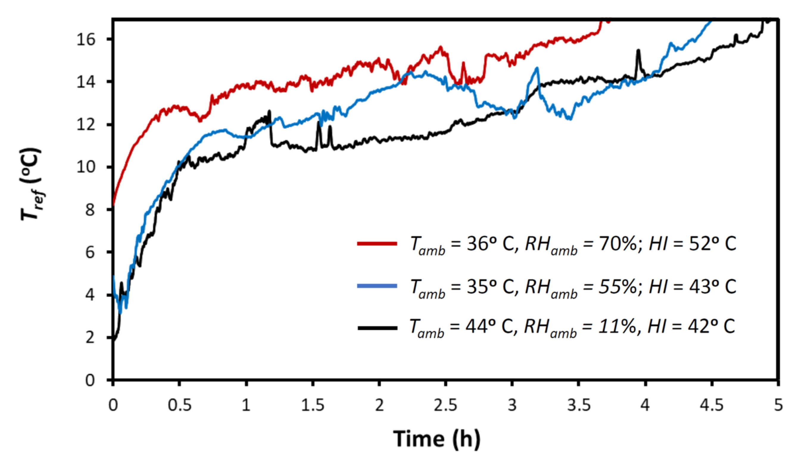
Tref recording were caused by spontaneous ice cube rearrangements as thawing proceeded. However, repeated measurements showed that variations in the time at which
Tref achieved the 17 °C value only varied within a 10 min range (data not shown). As expected,
Tref progressively increased, being <17 °C for 5 h in the example of hot dry desert condition (
HI = 42 °C), for 4.5 h in the hot humid example of tropical ambient conditions (
HI = 43 °C), and for 3.75 h in the condition of exceptional stress corresponding to
HI = 52 °C. Interestingly, the capability of the device to refrigerate the airflow was not limited to the times shown in
Figure 3 because, in all cases, at the end of the recording there was still ice remaining within the container. Remarkably, the similar values of airflow temperatures (
Tref) in
Figure 3 (at any time all measurements differ by less than ≈5 °C) show that the capacity of the setting for decreasing the airflow temperature scarcely depends on the ambient air conditions (
Tamb,
RHamb), although the duration of refrigeration (e.g., for
Tref < 17 °C) considerably decreases with
RHamb due to the energy required for air condensation (as predicted by the theoretical model equations).
Figure 4 shows an example of how the temperature of the airflow (at the vertical below the output orifice of the device) decreases with distance to the outlet orifice. Although the airflow temperature was 17.5 °C below
Tamb in the immediate vicinity of the outlet (≈0–5 cm), this temperature drop decreased progressively, being only 5.4 °C below
Tamb at a point 15 cm below the airflow outlet. This pattern of temperature dependence on distance and variability is consistent with turbulences and centerline velocity decay in a free jet [
26].
Figure 4 shows that, as expected, to optimize the cooling effect of the airflow, the distance from the air outlet to the infant should be reduced as much as possible. This figure also indicates that changing this distance can be a simple means to adapt the setting to the specific cooling needs of the infant.
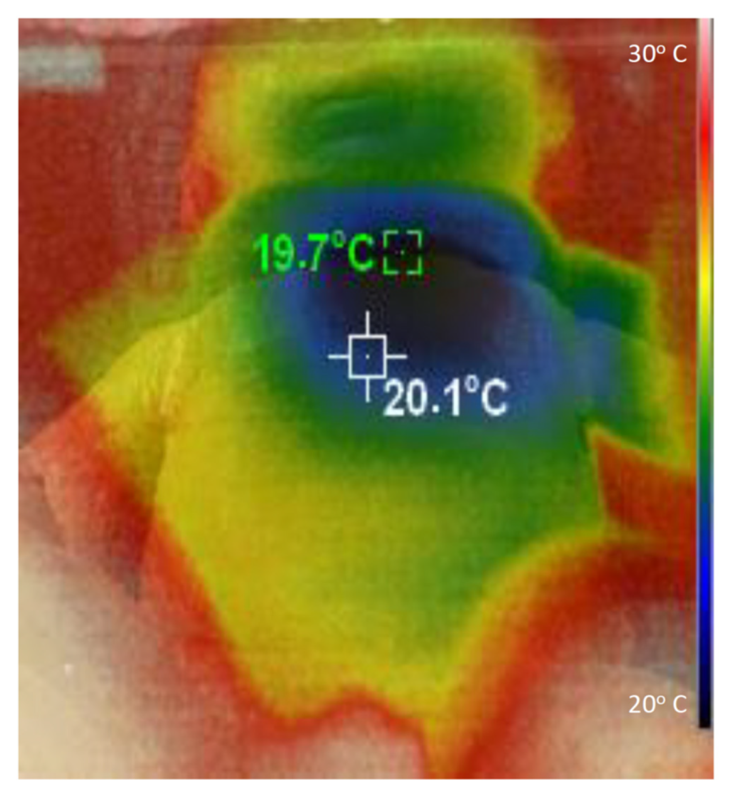
Figure 5 illustrates with an example how the refrigerated air is distributed on the body of the infant. This specific thermal image was taken when the airflow temperature
Tref was 24 °C below
Tamb, and the thoracic surface of the manikin was 8 cm below the airflow outlet. It is important to mention that measuring the temperature at the manikin surface simply serves to illustrate how the refrigerated airflow is distributed on the manikin, which has a geometry that realistically mimics that of an infant. The specific values of temperatures in
Figure 5 do not represent those that would be found on the skin of an infant because the energetically passive manikin does not dissipate metabolic heat or regulate its temperature.
4. Discussion
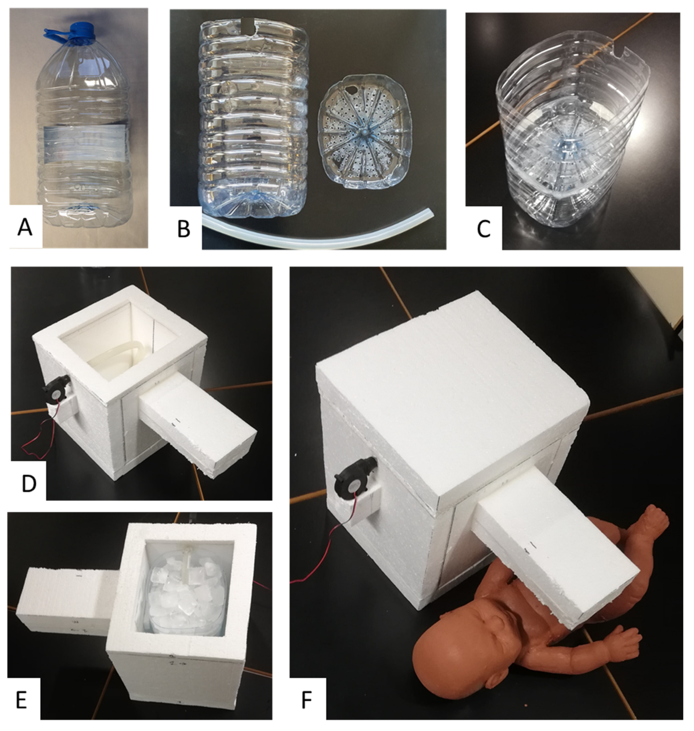
We here present the rationale, design and feasibility test of a new approach for generating a controlled flow of refrigerated air aimed at preventing dangerous hyperthermia in infants subjected to high temperatures and humidity conditions in LMICs. The theoretical model used to develop the device, as shown in Equations (1)–(11), includes all the energy transfer processes involved and allows any interested designer to dissect the roles played by the different dimensions and materials selected in the device’s construction. As a proof of concept, we built and satisfactorily tested a device that was extremely low cost and easy to fabricate by any layperson equipped with no tools other than a knife and glue (
Figure 2).
The approach in
Figure 1 is a practical alternative to other potential means of trying to reduce heat stress in infants when conventional air conditioning is not available. For instance, some proposed approaches at a community level in LMICs are to design buildings, e.g., nurseries, by optimizing architectural structure and materials [
27,
28]. However, these proposals are expensive, difficult to implement, and do not provide a solution at the individual home level. Regarding home-based approaches, it should be mentioned that the common solution of using a fan for alleviating heat stress is not satisfactory, and in most cases is clearly insufficient. Indeed, if
Tamb is slightly below 37 °C, using a fan and thus projecting air at such a high temperature on the infant skin would result in minimal heat loss by convection. Moreover, if
Tamb > 37 °C, using a fan would be counterproductive because it would increase heat transfer to the body by convection, further increasing the risk of infant dehydration. Using a cold water bottle is not cost-effective because a high fraction of the negative heat transfer from water is dissipated through the bed and does not reach the infant. Moreover, trying to refrigerate air by placing a pan or bowl with ice cubes in front of a fan has low effectiveness because most ice refrigeration capacity is lost by air dispersion. In fact, the procedure described in
Figure 1 is probably the most cost-effective way to achieve optimal negative heat transfer from ice to an infant.
It is worth noting that the conceptual approach in
Figure 1 can be implemented using different configurations. The key point is to allow the airflow to circulate in close contact with the ice surface to reach almost a thermal equilibrium before leaving the chamber. It should be noted that, as the device was designed to achieve the maximum possible negative heat transfer from a modest amount of ice to an infant, optimizing the design according to the model presented in Equations (1)–(11) is crucial to minimize the loss of refrigeration capacity. Specifically, it is important to reduce heat transfer through the walls of the chamber by using a highly isolating material, and by reducing unintended air leaks (using putty in the wall joints may be useful). As a proof of concept, we used expanded polystyrene because, given its low cost and excellent thermal isolation properties, it is widely used in packaging and building industries worldwide, and is therefore available in LMICs either commercially or by recycling from other applications. However, if not available, expanded polystyrene could be replaced by using several layers of common corrugated cardboard recycled from packaging boxes. Indeed, conventional corrugated cardboard has a thermal conductivity ≈2-fold greater than expanded polystyrene [
29], indicating that using a cardboard-based chamber wall with 2-fold thickness would provide similar thermal isolation as employing expanded polystyrene. Interestingly, the material of the ice/water container and hose within the chamber (
Figure 1) is not relevant because, as they are surrounded by the isolating wall, they play no role in heat exchange. This fact makes it easy to use any new or recycled container and tubing, as shown in the proof-of-concept example (
Figure 2). The blower we used was a very low-cost device that is commercialized as a spare component of 3D printers and is available by e-commerce (<EUR 3 retail cost via Amazon and an even lower cost via Alibaba). The blower can be operated by a conventional 12 V source (mains 110/220 V) or by any car/motorbike battery if the conventional power supply is compromised (given its 100 mA consumption at 12 V, any 45 A·h battery from a small car could provide energy for 18 days with 24 h continuous blower operation).
Some issues deserve to be mentioned regarding the practical application of the proposed device. As shown in
Figure 3, the airflow temperature
Tref of the refrigerated airflow leaving the device progressively increased over time. This was expected for a constant airflow
V’ because the amount of ice is progressively reduced. Technically, the cooling capacity of the setting can be easily modulated by incorporating a temperature sensor and a controller to regulate the voltage applied to the blower, but we intentionally avoided any complexity because we aimed to develop an extremely simple and cheap device. Interestingly, the cooling capacity of the setting can be adjusted manually in different manners. One of these is by modifying the distance from the airflow outlet and the infant (
Figure 4). Another could be to modify the airflow
V’ of refrigerated air using a power supply that can regulate the voltage provided to the blower (e.g., for the specific setting in
Figure 2, when the blower was powered by 9 and 12 V, airflow
V’ was 0.80 and 1.12 L·s
−1, respectively). In addition, and more simply, airflow can be modified by partially clam** the tube between the blower output and the chamber inlet to reduce
V’. For this purpose, instead of placing the blower close to the chamber as in
Figure 2F, a soft piece of hose could be used to connect the blower and the tube inside the chamber. As the simple device does not include a thermometer, the airflow temperature
Tref cannot be measured, as was done during testing in the laboratory. However, the temperature reaching the infant’s surface, which is the relevant temperature in practice, can be sensed by hand by the infant’s caregiver and modified accordingly. Given its simplicity and low cost, the device was not designed as a precise medical device, but rather as an individual tool to reduce the risk of hyperthermia in infants and young children living in homes and nurseries in LMICs under high thermal stress conditions because of lack of air conditioning.
It is interesting to note that a relatively low flow (e.g., 0.5 L·s
−1) of refrigerated air has a high potential for dissipating body heat in two ways. When this air is directly applied to the infant’s skin (at 37 °C), he/she will lose heat according to two mechanisms. Theoretically, the refrigerated air (e.g., at 10 °C), when in contact with the skin at 37 °C, will be rapidly heated to this temperature and, hence, according to Equation (2), it will extract heat from the body at a rate of 16.2 W. Moreover, the refrigerated air at 10 °C, although it is saturated with water vapor when leaving contact with the ice, has a relatively low vapor content; hence, when it is heated by contacting the infant’s skin, it can evaporate a considerable amount of water from transpiration, thereby extracting further heat from the body. In fact, as derived from the previous theoretical equations, the refrigerated air in the example has the potential of extracting 25.6 W of heat by evaporation. By adding the potential heat transfer at the skin level, via air heating and water evaporation, 0.5 L·s
−1 of saturated air at 10 °C air can extract up to 41.8 W from the infant. Remarkably, this refrigerating power is ≈2-fold the typical total resting metabolic rate of an infant weighing 6 kg (19.4 W = 67 kcal·kg
−1·day
−1) [
30] which, in turn, is greater than his/her heat dissipation rate. Therefore, even if the refrigeration efficiency of the projected airflow on the infant’s skin is considerably below 100%, the device should have enough capacity to prevent infant hyperthermia. However, future studies are required to assess the clinical effectiveness of the approach in infants.


 ,
, 


