1. Introduction
There are many attractive benefits of the interior permanent magnet synchronous motors (IPMSMs), including the high-power density, high acceleration capability and broad speed operating range. Therefore, IPMSMs have been widely used in industries and transportations [
1]. Nevertheless, the internal system parameter variations and unmodeled dynamics resulting from magnetic saturation, especially the inductances of the IPMSMs, will induce time-varying and nonlinear control characteristics of the IPMSMs. Thus, the development of parameter estimation techniques is significant to achieve reliable and high-precision field-oriented control performance for the IPMSMs [
2,
3,
4,
5,
6,
7,
8].
According to the process of parameter estimation, the methods of parameter estimation can be mainly divided into two categories, the offline parameter estimation [
2,
3] and the online parameter estimation [
4,
5,
6,
7,
8]. Generally, the offline methods demand a large amount of resources. The analyses of large quantities of data for different frequencies, voltages or currents are also necessary. Moreover, the variations of the
dq-axis inductances with different load current and magnetic saturation can only be employed by using lookup tables. On the other hand, several online parameter estimation techniques have been developed to overcome the difficulties of the offline methods, and can obtain the machine parameters without using the lookup tables [
4,
5,
6,
7,
8,
9], and which can be further divided into the non-intrusive methods without signal injection [
4,
5,
6] and the intrusive methods with signal injection [
7,
8,
9]. A parameter estimation method composed of two affine projection algorithms (APAs) was proposed in [
4]. Furthermore, two recursive least square (RLS) algorithms have been developed and employed the dynamic model of the machine in the
dq reference frame in [
5]. In addition, a method using the derivatives of the measured dc-bus voltage and stator current of the inverter during each PWM cycle to estimate machine inductances was introduced in [
6]. However, estimating the parameters by using two RLS algorithms or APA is not straightforward, and improper estimation convergence is possible owing to measuring errors. Regarding the online parameter estimation strategies with signal injection, a current injection-based methodology considering the VSI nonlinearity and magnetic saturation has been introduced in [
7]. Additionally, based on self-adaptive step size APA, using square-wave current injection was proposed in [
8] for online parameter estimation. The disadvantage of the online parameter estimation methods using the injection signal is that the injected signals could increase the current and torque ripples and result in the deterioration of the control performance of motor drives. Nevertheless, the merits of the signal injection are easy implementation and no need for the addition of extra hardware devices [
9].
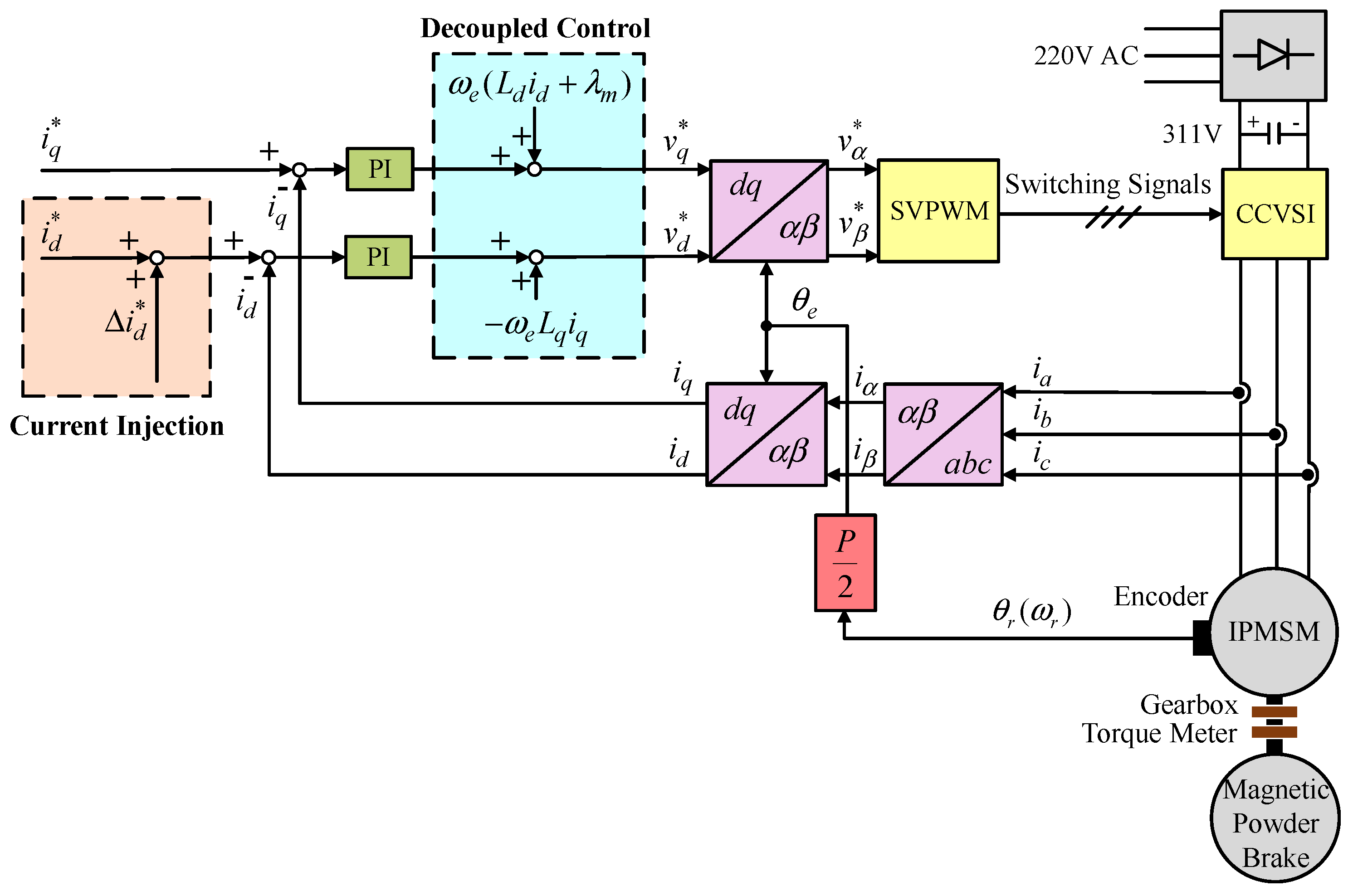
In a field-oriented control (FOC) IPMSM, the effectiveness of the decoupled control the current-controlled voltage source inverter (CCVSI) depends on the correct values of the machine parameters. However, the machine parameters will vary due to magnetic saturation. Therefore, an online parameter estimation methodology using
d-axis current injection is proposed for the IPMSM in the constant torque region. The smoothing values of
dq-axis voltages, currents and electrical rotor speed are employed for the estimation. The above method can effectively eliminate the influence of measuring errors of voltages, currents and rotor position on estimation. Moreover, the proposed parameter estimation method can estimate the distorted voltage of the CCVSI, the varying
dq-axis inductances and the rotor flux real time. Since the simplified inductance model proposed in [
7] will result in inaccurate unsaturated inductance estimation, a new methodology of estimating the unsaturated inductance using the maximum torque per ampere (MTPA) theory combining with the RLS algorithm is proposed in this study. Furthermore, to shorten the estimation time, the distorted voltage is estimated by an analytical equation. In addition, the injected
d-axis current is elaborately devised to reduce the influence on the control performance of the IPMSM drives. The estimation algorithms are developed deliberately to accomplish a straightforward flowchart which can ease the effort of practical implementation.
Since the MTPA control can improve the torque output in the constant torque region of an IPMSM, there are some published methods of MTPA in recent years [
10,
11,
12,
13,
14]. In [
10], a fuzzy control system adopting the high-frequency mechanical power change information was developed to acquire the advance angle for the MTPA scheme of an IPMSM. In [
11], a small virtual current angle signal was injected to produce the
d-axis current demand as well as to follow the MTPA operation point with the adoption of the internal properties of the MTPA. Moreover, in [
12], a novel MTPA algorithm does not make use of any equations and motor parameters were proposed. In order to minimize the magnitude of the stator current vector at the given load torque, the current phase is varied continuously. In [
13], a constant parameter MTPA strategy was proposed to control the permanent magnet-assisted synchronous reluctance motors. In addition, the machine learning approach was used to design the MTPA and flux-weakening control for an IPMSM in [
14]. The
d-axis current command can be varied downward gradually as proposed in [
14] to find the lowest value of the stator current at a specific operating condition, i.e., the MTPA operating point which could satisfy that specific operating condition. Therefore, the MTPA method proposed in [
14] is adopted in this study to find the lowest value of the stator current at a specific operating condition.
Since the control performance of the outer velocity loop or position loop is dependent on current regulation, the design of the bandwidth of the inner current loop is important [
15]. In the digital control alternative current (AC) servo system, the bandwidth of current loop depends on switching frequency, plant parameters and the delay times, including sampling, pulse width modulation (PWM), filter, and calculation. Several approaches have been developed to enhance the bandwidth of current loop or current control ability of the permanent magnet synchronous motor (PMSM) drives [
16,
17,
18,
19,
20]. These methods can improve the control performance, transient response, and robustness against machine parameter variations. Moreover, intelligent controllers using various neural networks are very effective to improve the robustness and performance of the synchronous motor drives due to their online learning, generalization, and parallel processing control characteristics [
21,
22]. Therefore, to improve the control performance and bandwidth of the current loop of the IPMSM drives, an intelligent proportional-integral-derivative (PID) neural network controller proposed in [
23], with improved online learning algorithm, is developed in this study to replace the traditional PI controller for the current-loop control. Furthermore, the estimated
dq-axis inductances and magnetic flux of the rotor are adopted in the decoupled control of the current loops to assure the effectiveness of the FOC IPMSM drive.
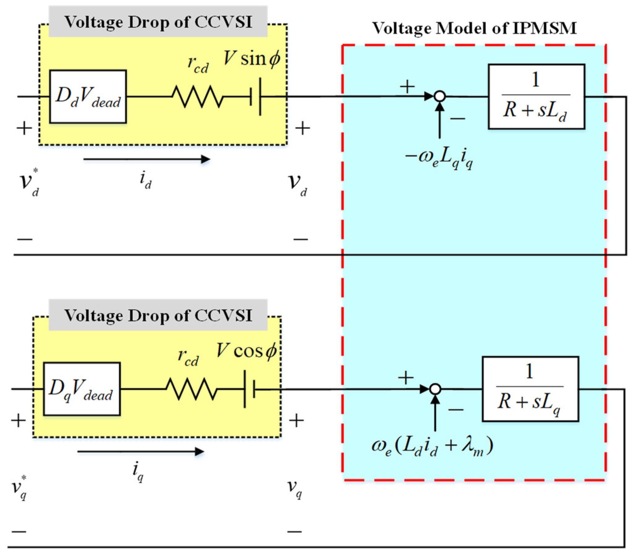
The rest of this study is organized as follows. In
Section 2, first, a voltage model of IPMSM based on
d-axis current injection considering the nonlinearity of a CCVSI is proposed. Second, the online estimation of the CCVSI distorted voltage is derived. In
Section 3, during current injection, a simple linear model is developed to model the cross- and self-saturation of the
dq-axis inductances. Then, the parameters of the linear model are estimated by using the RLS method. Moreover, the tuning method for the
d-axis unsaturated inductance is proposed by using the theory of the MTPA with the combination of the RLS method. In
Section 4, the estimated
dq-axis inductances and magnetic flux of the rotor are then adopted in the decoupled control of the current-loop control. Furthermore, the intelligent PID neural network controller is employed to improve the control performance and bandwidth of the current loop. In addition, various operating conditions are investigated to verify the effectiveness of the proposed online parameter estimation methodology and the bandwidth improvement of current loop using the intelligent PID neural network controller in
Section 5. Finally, some conclusions are presented in
Section 6.
3. RLS Parameter Estimation Methodology
The cross-saturation effect is much smaller than the self-saturation effect owing to the small magnitude of injected
d-axis currents. Therefore, one can assume the cross-saturation to be zero in order to simplify the estimation in practical implementation. Thus, during current injection, the linear Equations (17) and (18) are adopted to model the self-saturation of
dq-axis inductances as follows:
where
and
are the
d-axis and
q-axis unsaturated inductances;
and
are the
d-axis and
q-axis self-saturation constants. Substituting (17) and (18) into (15) and (16), the following equations can be obtained:
The adopted RLS algorithm is listed in (21) as follows:
where subscript
k is the number of iterations;
and
are known model parameters and
is the model parameters to be estimated, which are depicted as follows:
Additionally,
can be estimated by using the 2nd order RLS algorithm. Since the
d-axis unsaturated inductance
is difficult to obtain by merely using the RLS, a novel tuning method for the
d-axis unsaturated inductance is proposed by using the theory of the MTPA. The lowest value of the stator current, i.e., the MTPA operating point which could satisfy a specific operating condition in terms of speed and load torque, could be obtained by varying the
d-axis current command gradually [
14]. The resulted
d-axis current which can lead to the lowest value of the stator current is defined as
. Moreover, the electromagnetic torque equation is differentiated with respect to the
q-axis current and the derivative is set to zero. Then, the extreme value can be obtained, and resulted in the
d-axis current command of MTPA as follows [
14]:
where
is the estimated value of
by using
. If
is not equal to
,
in (18) is adjusted online by using the equation shown below which is derived from (23):
The new value of
after adjustment is then substituted into (22), and the RLS algorithm is performed again to estimate the model parameters. The above process is processed continually until
. Moreover,
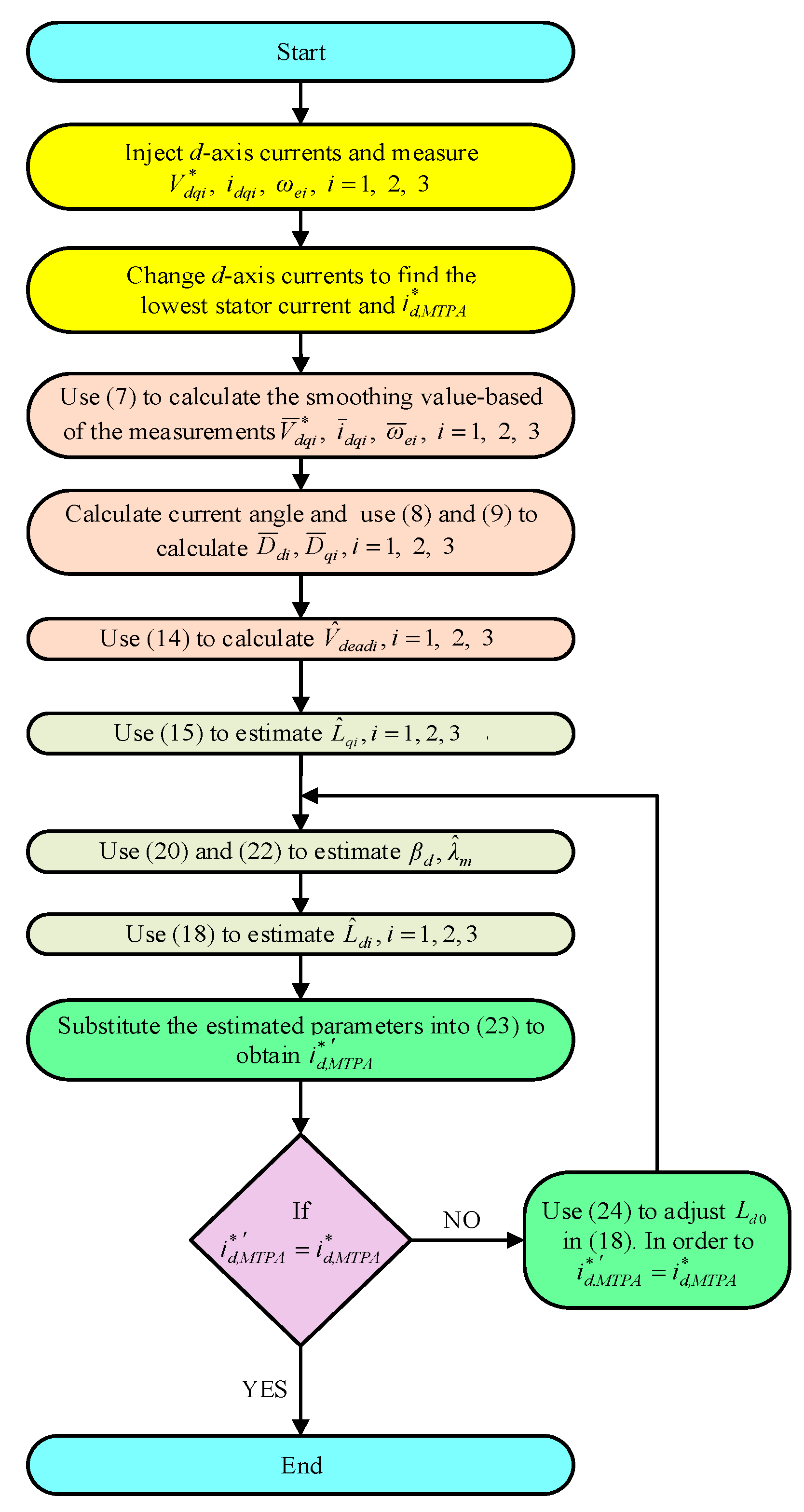
Figure 4 is the flowchart of the proposed estimation algorithm. In order for the proposed estimation algorithm to be better adopted in practical applications, detailed execution steps of the proposed estimation algorithm are described as follows:
- (1).
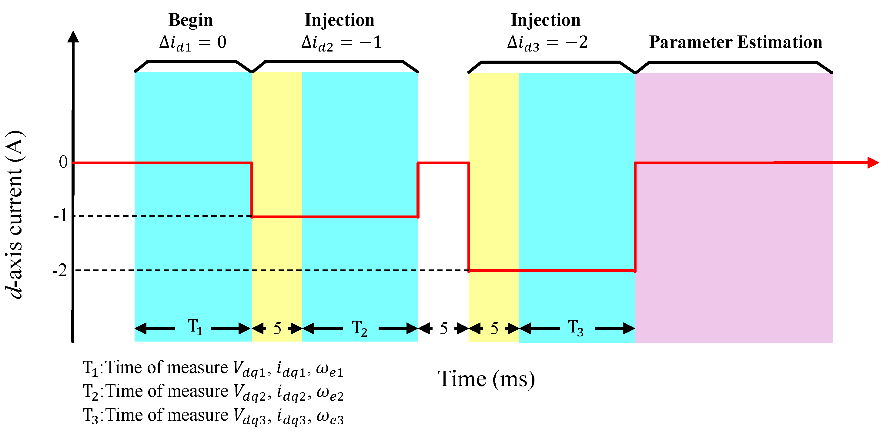
Current injection: Inject d-axis currents and measure , i = 1, 2, 3.
- (2).
Finding the lowest stator current: Change d-axis currents to find the lowest stator current and .
- (3).
Smoothing: Use (7) to calculate the smoothing value-based of the measurements , i = 1, 2, 3.
- (4).
Calculating distorted coefficients and voltage: Calculate current angle and use (8) and (9) to calculate , i = 1,2,3. Moreover, use (14) to calculate , i = 1, 2, 3.
- (5).
q-axis inductance estimation: Use (15) to estimate , i = 1, 2, 3.
- (6).
Parameters estimation: Use (20) and (22) to estimate , and use (18) to estimate , i = 1, 2, 3.
- (7).
Verification: Substitute the estimated parameters into (23) to obtain to check if or not. If not, go to next step. If yes, then end the algorithm.
- (8).
Adjusting: In order to achieve , use (24) to adjust in (18) and then go back to step 6.
The details of the implementation will be discussed in
Section 5.
4. Current-Loop Control Using PID Neural Network Controller
The estimated
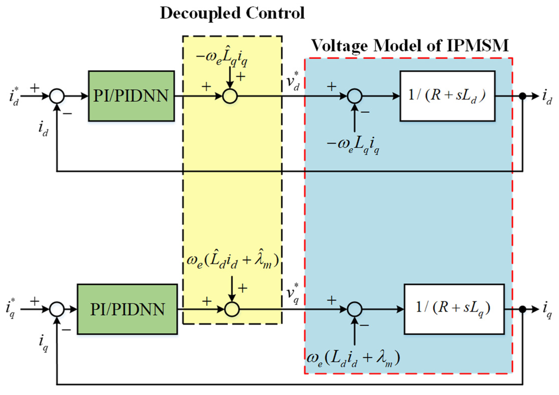
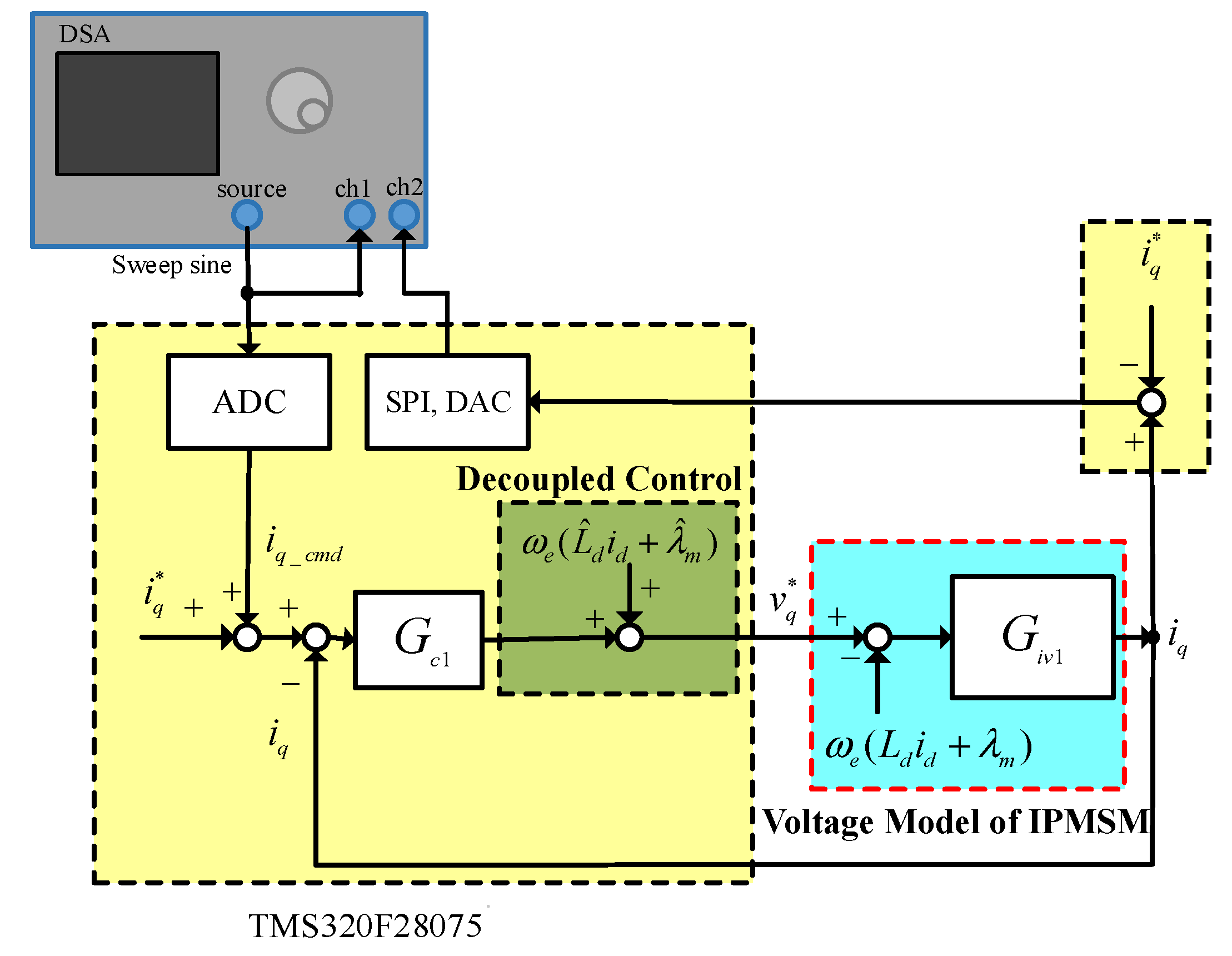
dq-axis inductances and magnetic flux of the rotor are then adopted in the decoupled control of the current loop as shown in
Figure 5, where the PID neural network is represented as PIDNN. Moreover, to improve the control performance and bandwidth of the current loop, an intelligent PID neural network controller proposed in [
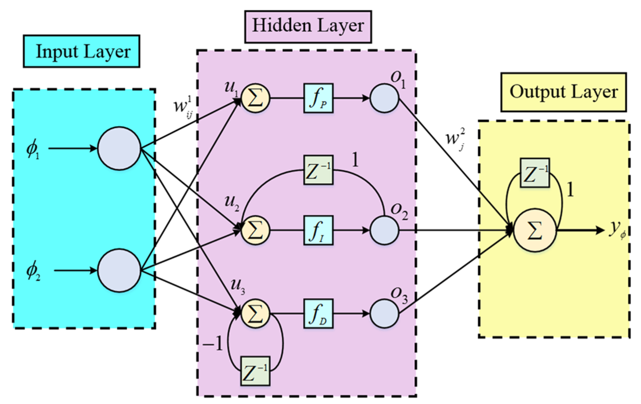
23] with improved online learning algorithm is adopted to replace the traditional PI controller for the current-loop control. The PID neural network is a three-layered structure. Starting from the two input nodes, it comprises an input layer, a hidden layer, an output layer, and finally an output node, as shown in
Figure 6.
Furthermore, the basic function of each layer and the signal propagation of the neural network are introduced as follows:
The input layer of the PID neural network are designed as:
where
N represents the
N th iteration;
.
The input of the hidden layer are the performance measures
, which can be represented as:
The outputs of the hidden layer
through the respective proportional, integral, and derivative paths can be calculated as follows:
The output layer can be represented as:
The first step to design the online learning algorithm of the PID neural network using the supervised gradient decent method is to define an energy function as follows:
Then, the learning algorithm is described as follows:
The error term to be propagated is given by:
and the connective weight
is updated by the amount:
where the factor
is the learning rate for
. The connective weight
is updated according to the following equation:
By using the chain rule, the connective weight
is updated by the amount:
where the factor
is the learning rate for
. The connective weight
is updated according to the following equation:
Moreover, to reduce the calculation burden of the DSP, the propagation term
can be defined as follows [
23]:
However, (38) will make the
shown in (34) always positive. Therefore, the concept of delta learning rule is adopted and (34) is improved and modified as follows:
That is to say, the online tuning of
is according to the derivative of the output of the PID neural network. In addition, the convergence analysis of the adopted PID neural network can be found in the
Appendix A.


