
Capacitor Current Feedback-Based Active Resonance Dam** Strategies for Digitally-Controlled Inductive-Capacitive-Inductive-Filtered Grid-Connected Inverters

 ,
, 
Abstract
:
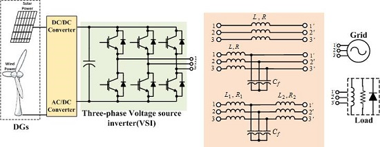
1. Introduction
- 1)
- To filter out all of the inverter output harmonics except for the fundamental frequency.
- 2)
- To have a cut off frequency much less than the switching frequency of the VSI (which typically should be lower than 0.1 of the switching frequency).
- 3)
- To limit the value of the filter inductances in order to reduce voltage drop and increase voltage transfer ratio at the rated current and also improve the voltage quality (by taking a low di/dt for large switching current ripples).
- 4)
- To minimize the total reactive power under the rated condition in order to ensure high power factor (should normally be limited to lower than 5%–10% of rated power).
2. Stability Analysis for Single-Loop-Controlled Inductive-Capacitive-Inductive-Filtered Grid-Connected Inverter with Different Resonant Frequencies
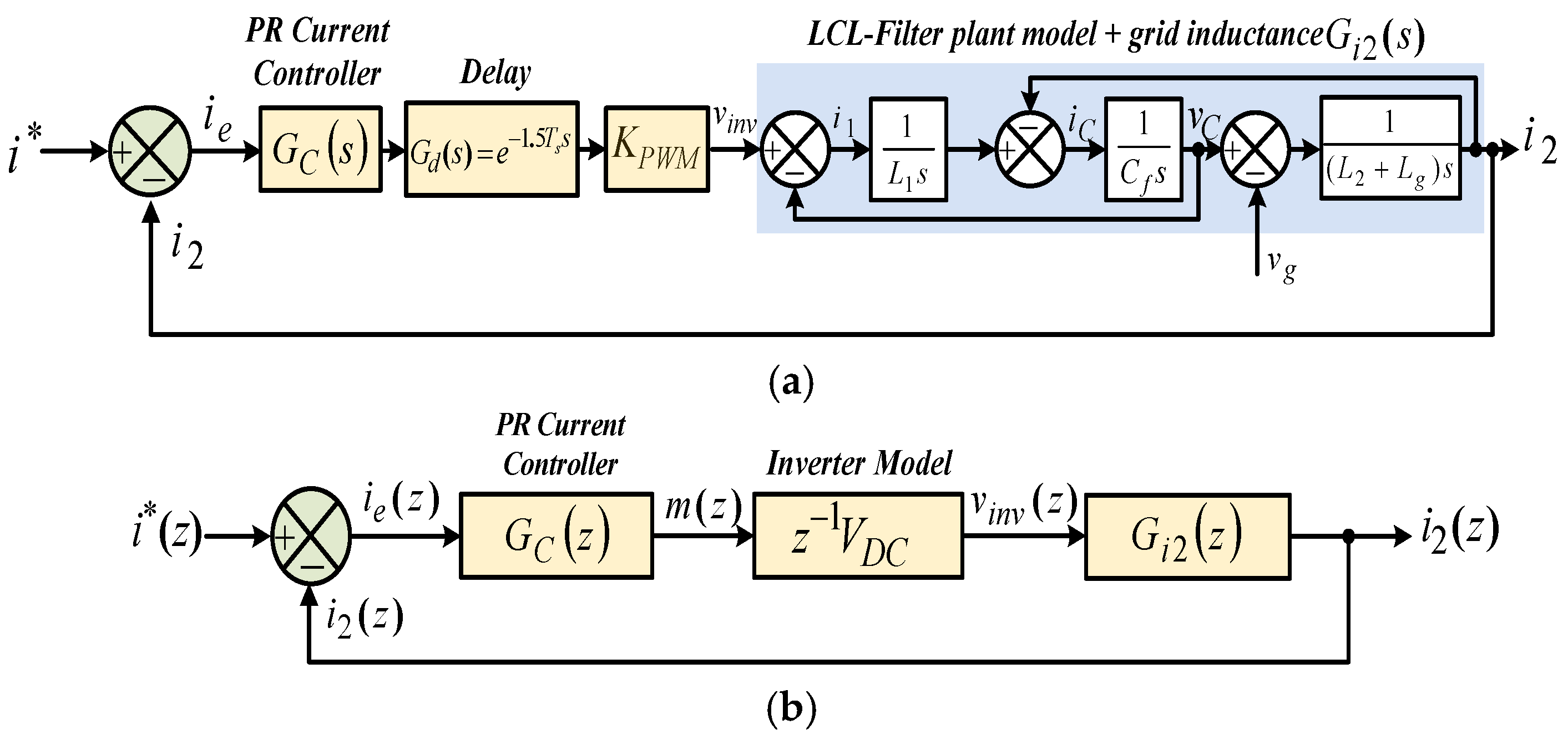
2.1. Single-Loop Grid-Side Current Control Strategy in Discrete-Time Domain
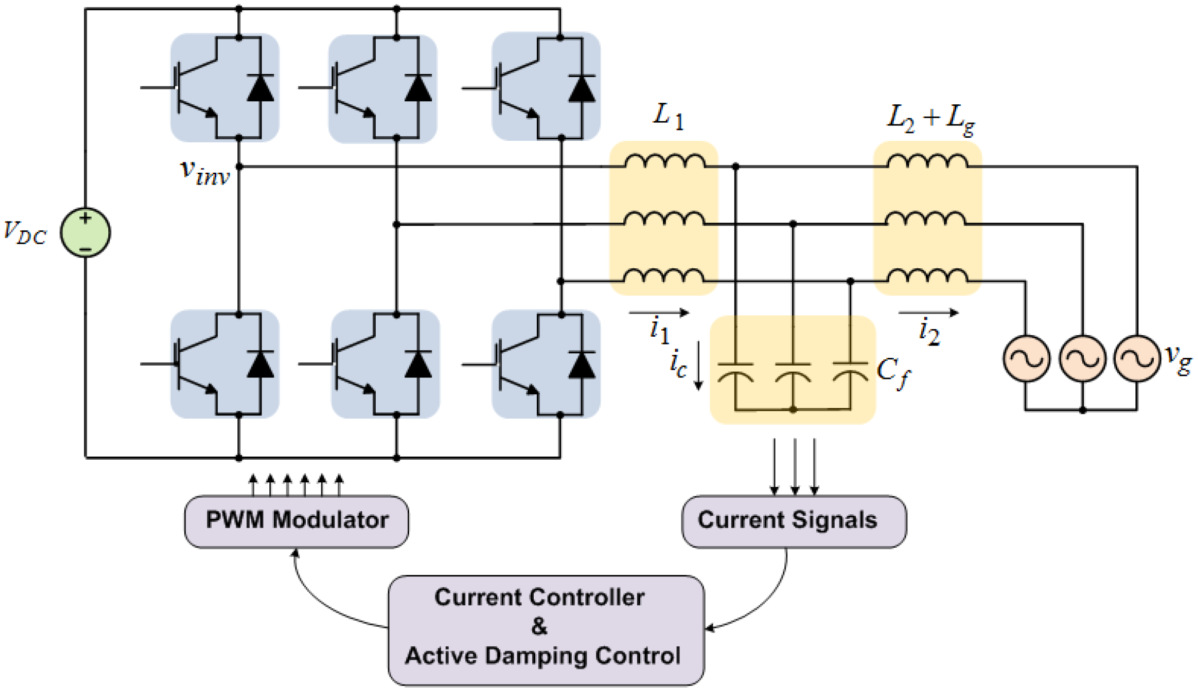
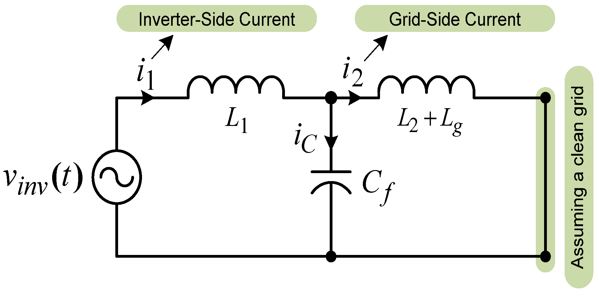
2.1.1. System Description
2.1.2. Stability Analysis
2.2. Current Controller Gains Determination for High Resonant Frequency Region
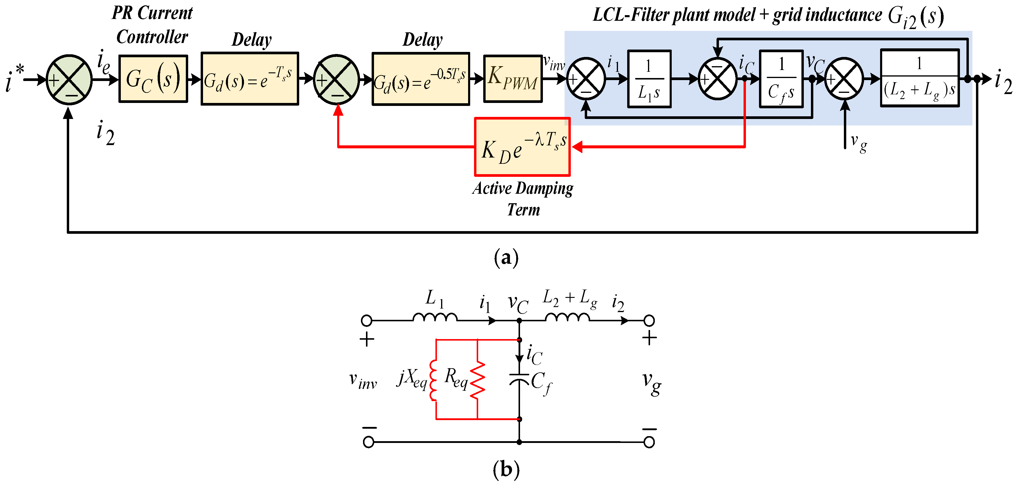
3. Proportional Capacitor Current Feedback Active Dam** Approach
3.1. Impedance-Based Analysis
3.2. Computation and Pulse Width Modulation Delays Effect on the Resonance Dam** Performance
- 1)
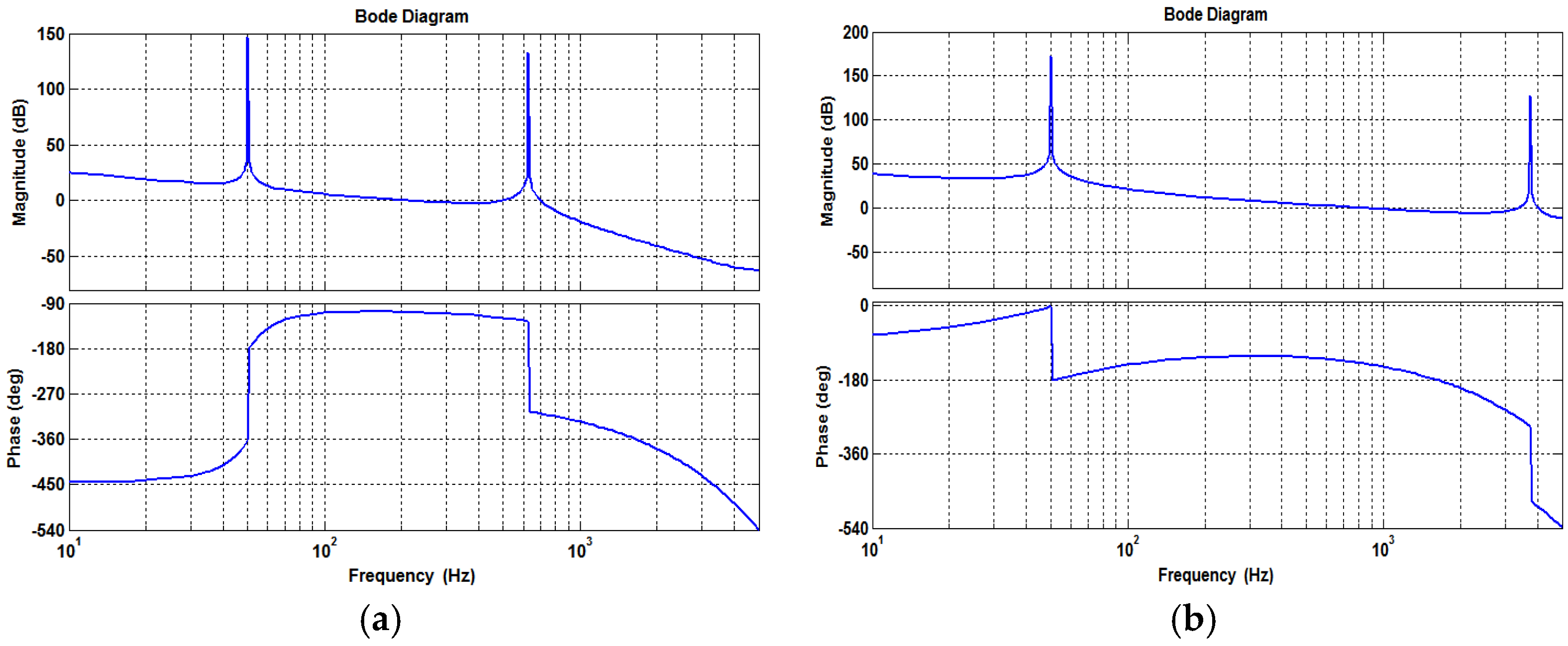
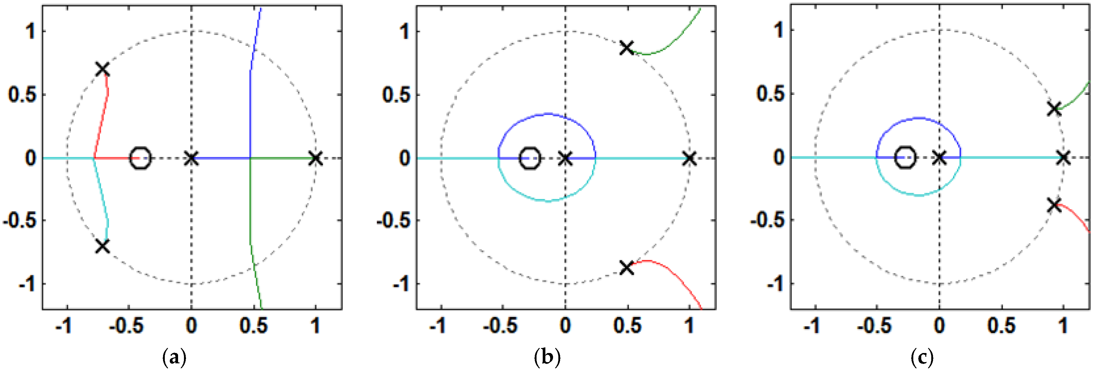
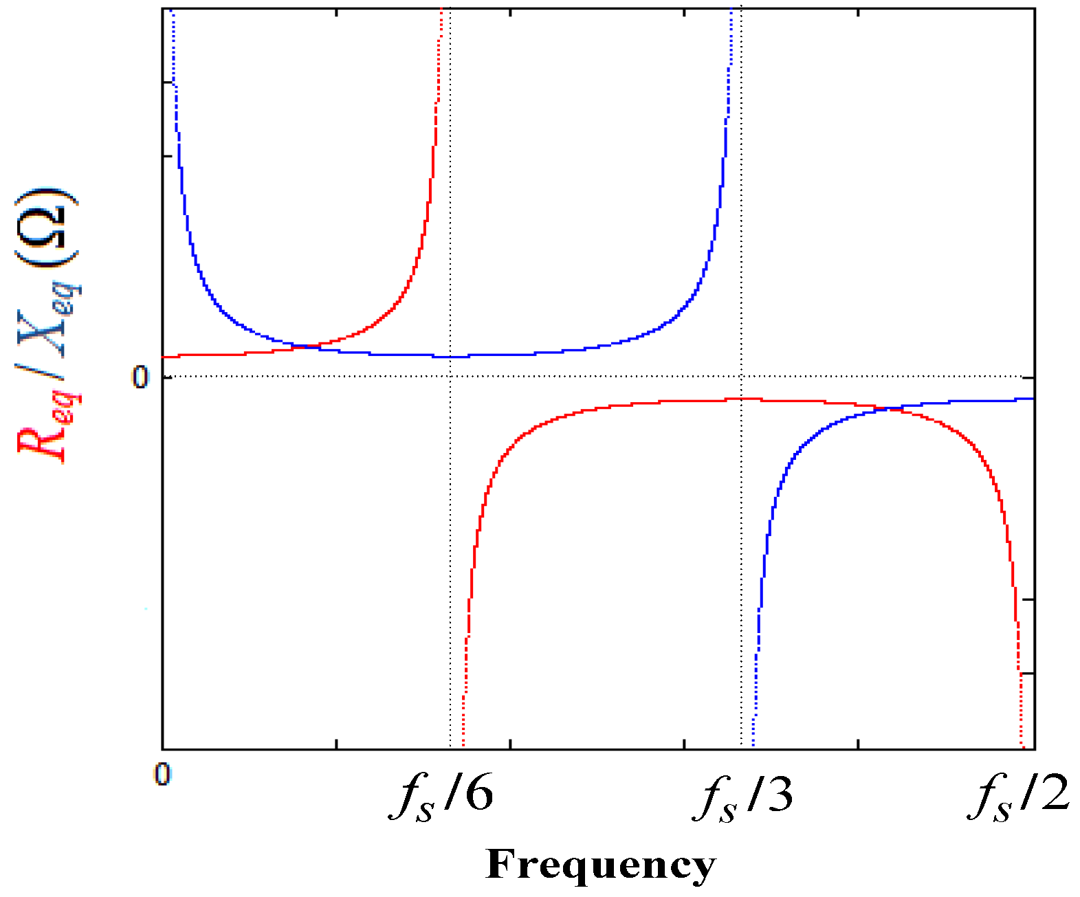
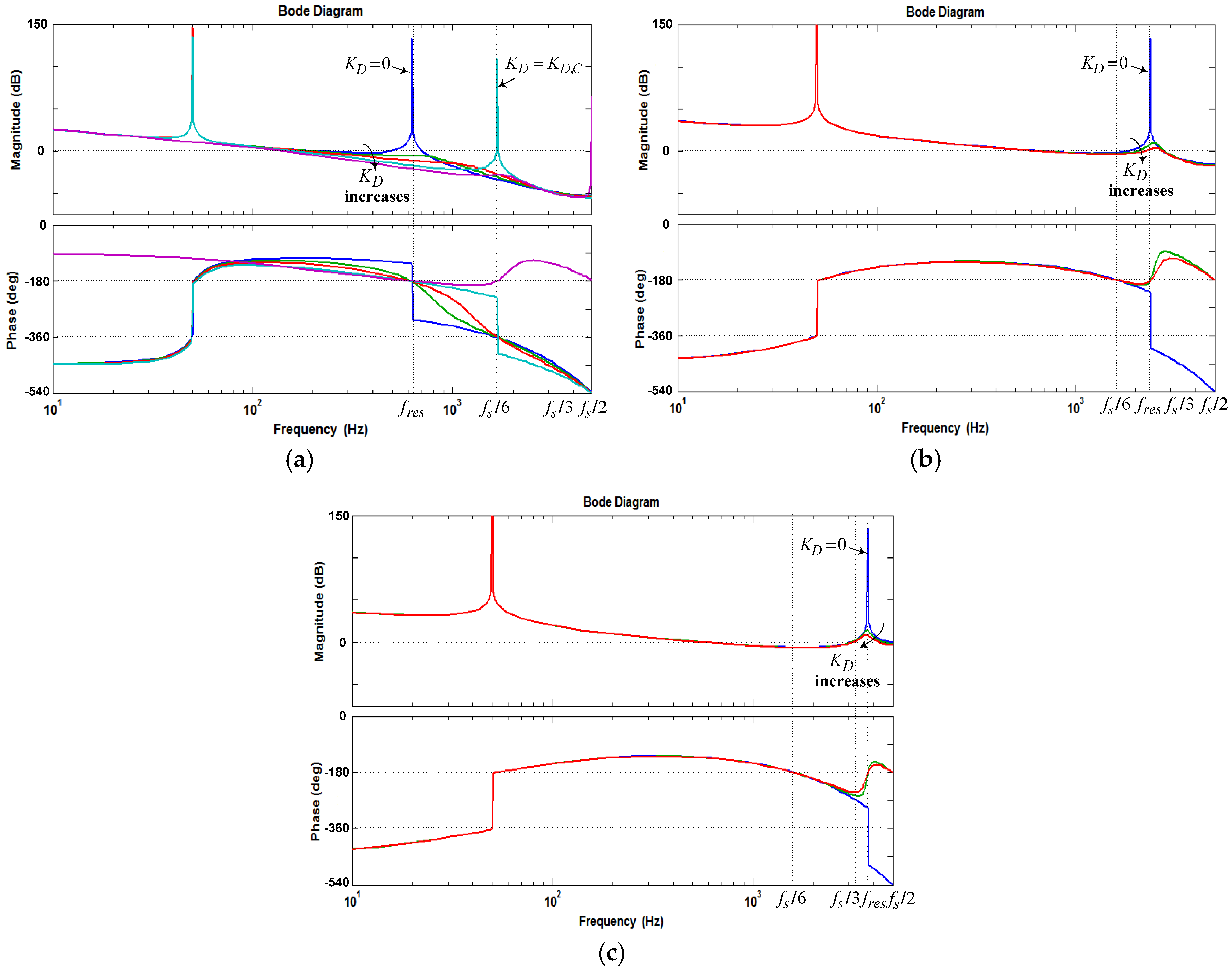
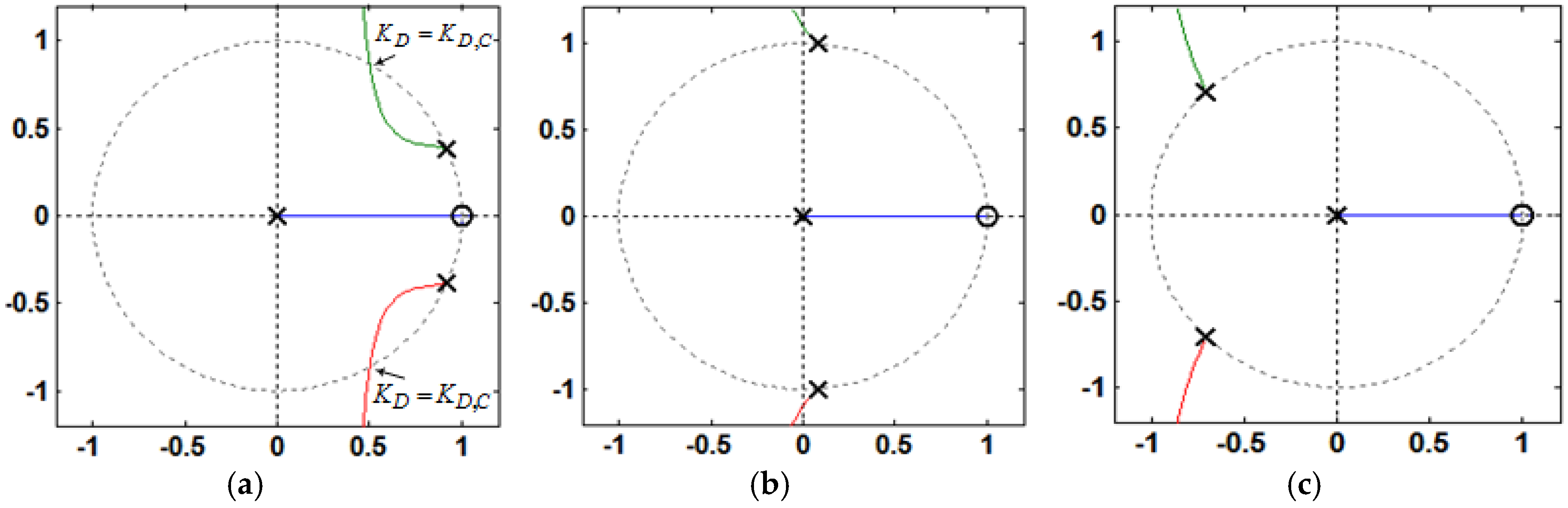
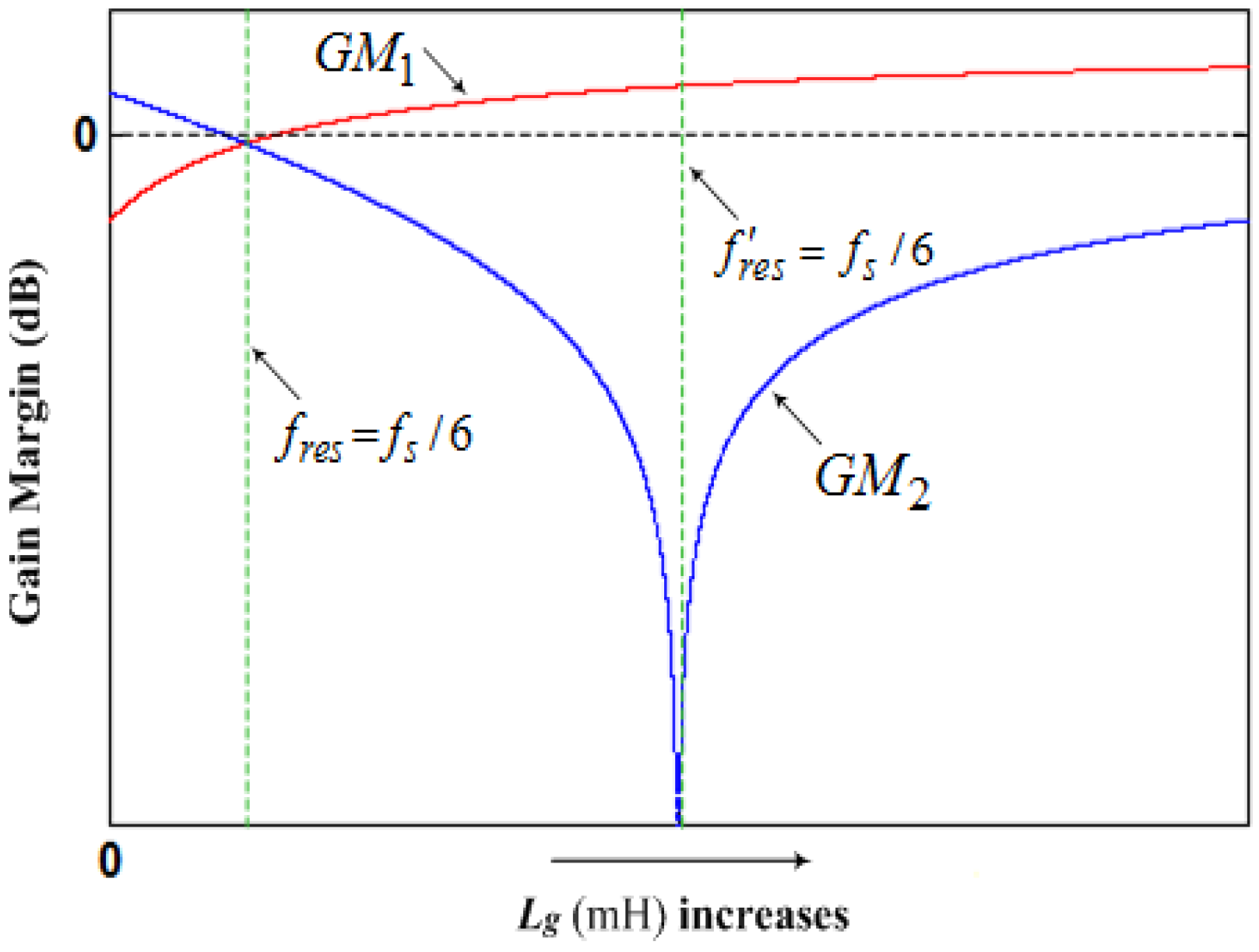
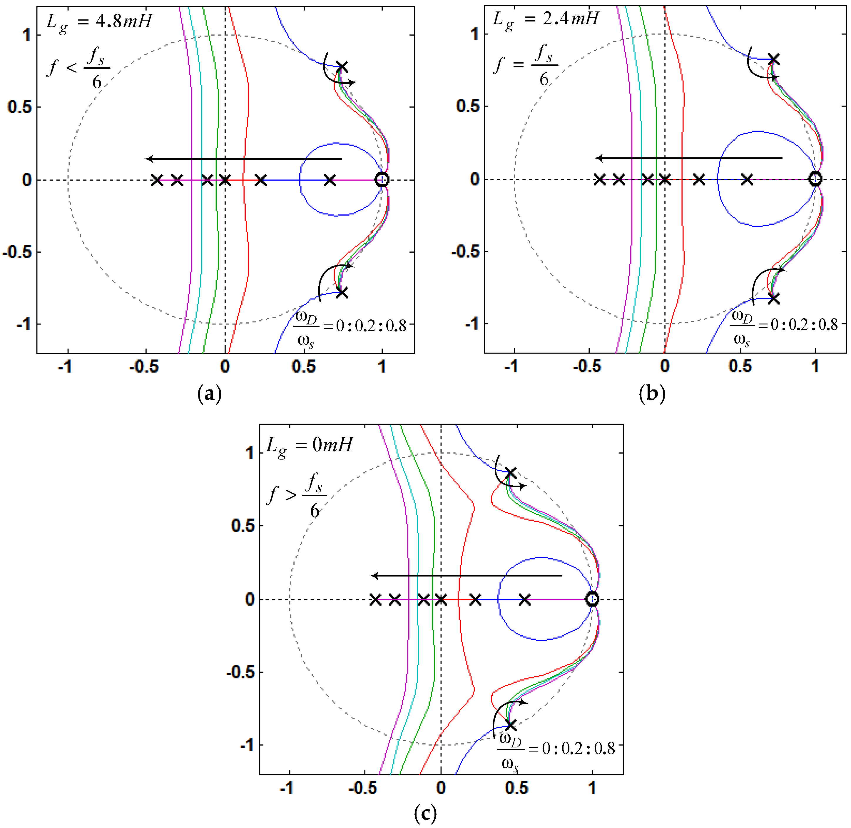
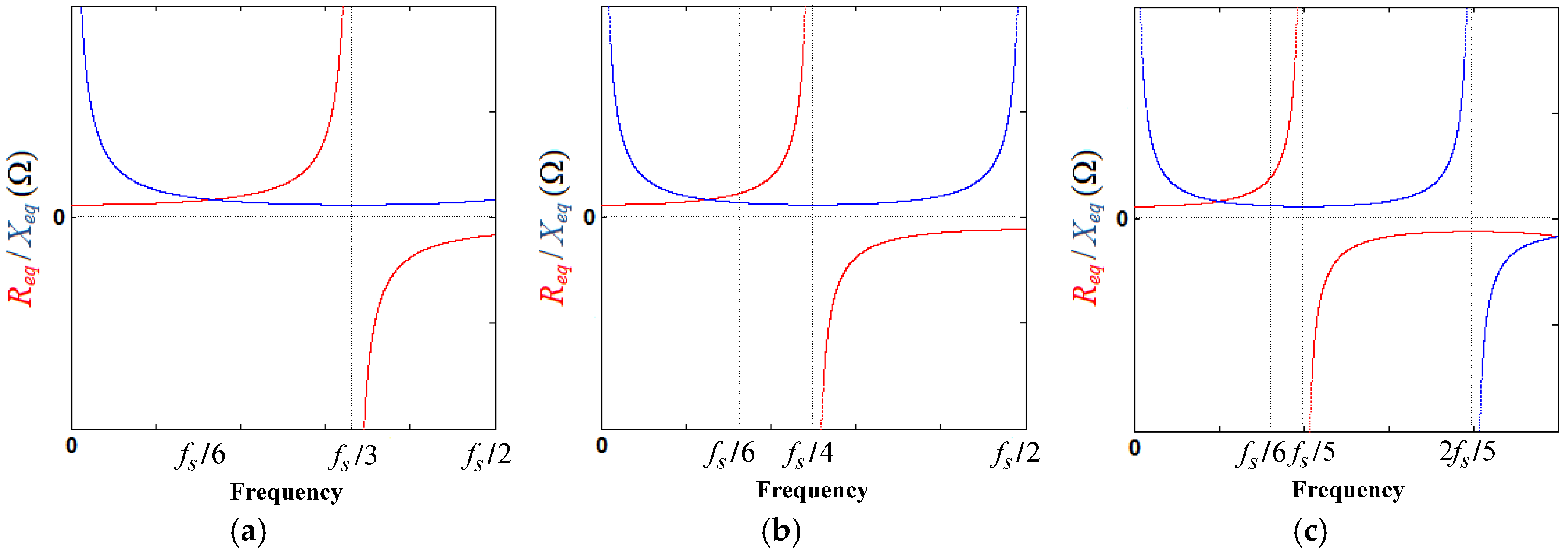
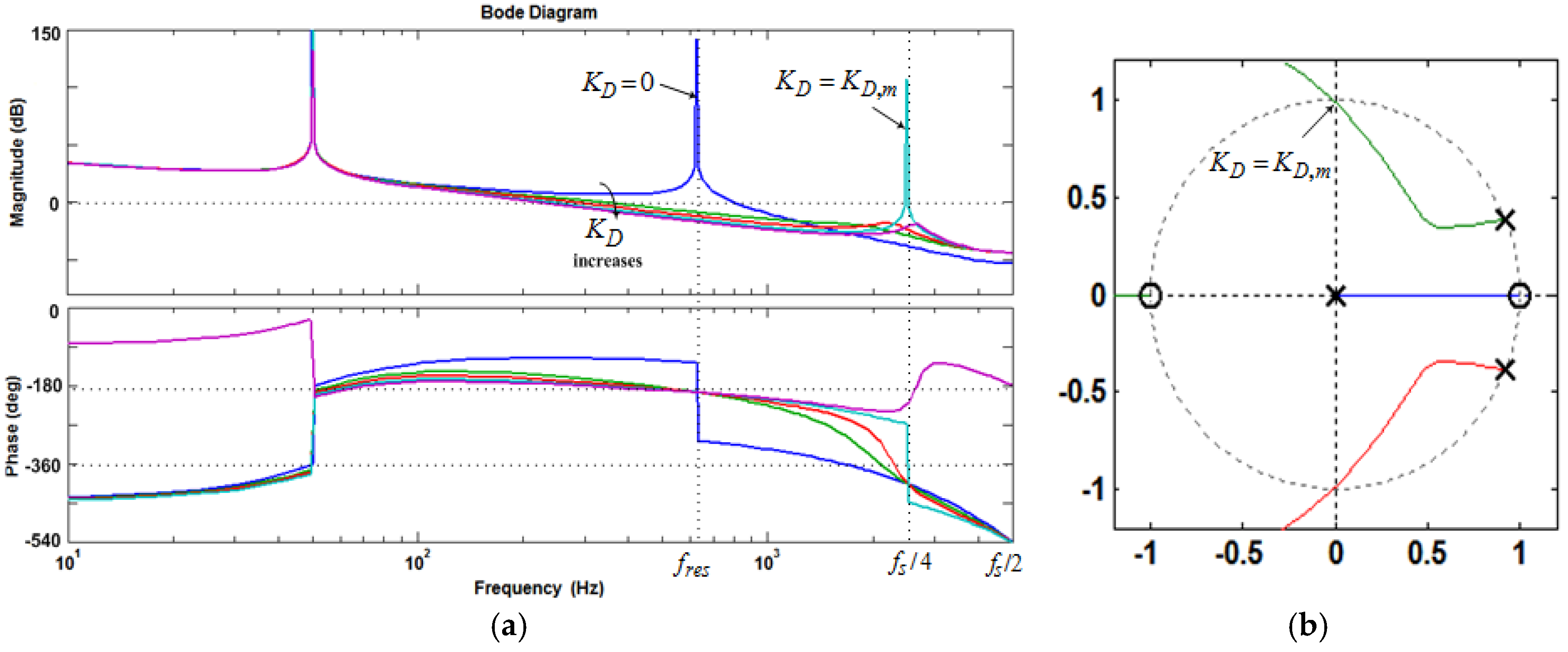
- If fres < fs/6 and 0 < KD < KD,C, i.e., < fs/6, Req is positive at (Figure 9), and no open-loop unstable poles exists, as seen in Figure 11a. Hence, the phase plot crosses over −180° only at fres in the direction of phase decrease as shown in Figure 10a. In addition, if fres < fs/6 and KD = KD,C, i.e., = fs/6, Req is infinite at (Figure 9), and no open-loop unstable poles exists, as seen in Figure 11a. In this case, it has no contribution to the resonance dam** performance, and the phase plot also crosses over −180°only at fres in the direction of phase decrease (Figure 10a). As it is known well, for evaluating the stability, in the open-loop Bode diagram, the frequency ranges with amplitude above 0 dB must be investigated. In these frequency ranges, a −180° crossing in the direction of phase increase is considered as a positive crossing N+ if the gain margin at that −180° crossover frequency is smaller than 0 dB, and a −180° crossing in the direction of phase decrease is considered as a negative crossing N− if the gain margin at that −180° crossover frequency is smaller than 0 dB [42,50]. According to the Nyquist stability criterion [50], to ensure the system stability, the value of 2(N+ − N−) must be equal to the number of the open-loop unstable poles, otherwise, the system gets unstable. For fres < fs/6 and 0 < KD ≤ KD,C, i.e., ≤ fs/6, the value of (N+ − N−) is equal to zero since the gain margin at −180° crossover frequency (fres) is greater than 0 dB, as seen from Equation (34) (in dB). This means that the system will be stable in this frequency region:For KD = KD,C, Cf = 36 μF, Kp = 0.0261, and L2 = Lg = 1.8 mH, the gain margin GM1 in dB is 33.565.
- 2)
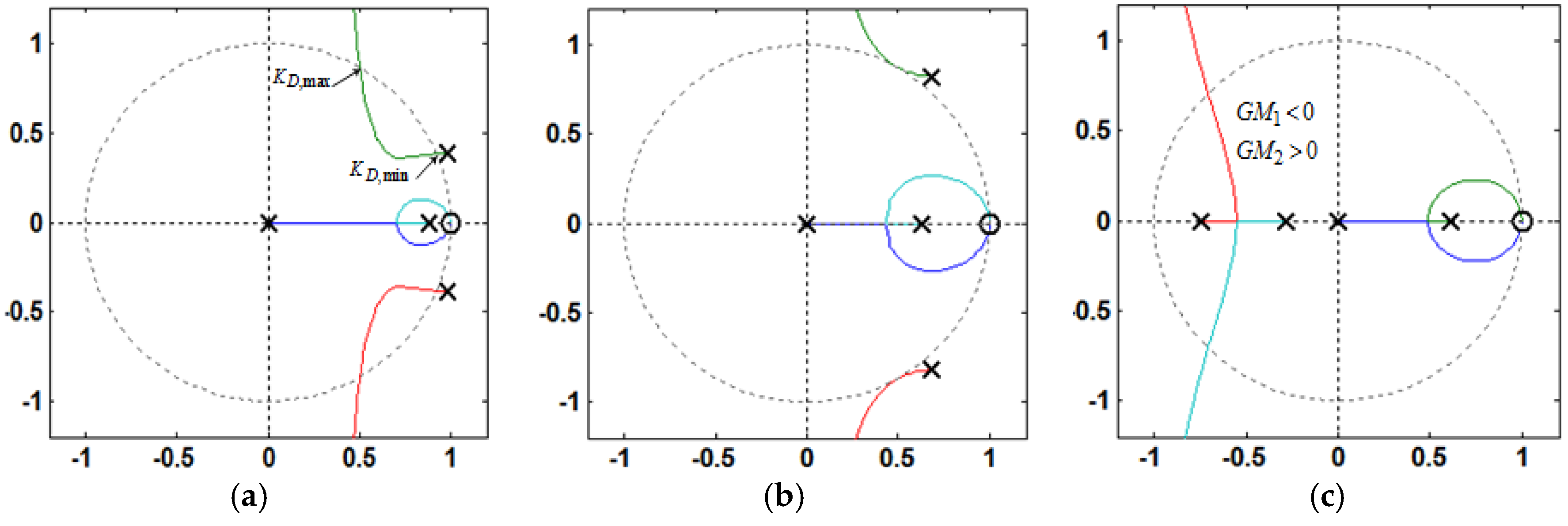
- If fres < fs/6 and KD > KD,C, i.e., > fs/6, Req is negative at (Figure 9), and a pair of open-loop unstable poles appears (non-minimum phase behavior in the closed-loop response), as seen in Figure 11a. In this case, the phase plot crosses over −180° both at fres and fs/6, respectively, in the direction of phase decrease and phase increase as shown in Figure 10a. Hence, according to the Nyquist stability criterion, to ensure the system stability, the value of 2(N+ − N−) must be equal to 2. It means that the gain margin at fres and fs/6, respectively, must be greater and smaller than 0 dB (GM1 > 0 dB and GM2 < 0 dB), i.e., N− = 0 and N+ = 1. The gain margin in dB at fs/6 can be derived from Equation (29) as Equation (35). By comparing Equations (34) and (35), one can easily understand that GM1 and GM2 will be equal, if fres = fs/6:
- 3)
- If fres ≥ fs/6 and KD > 0, i.e., > fs/6, Req is negative at (Figure 9), and a pair of open-loop unstable poles appears, as seen in Figure 11b,c. In this case, the phase plot crosses over −180° both at fs/6 and fres, respectively, in the direction of phase decrease and phase increase as seen in Figure 10b,c. Hence, to stabilize the system, GM1 < 0 dB and GM2 > 0 dB are both needed.
3.3. Robustness Evaluation Against the Grid-Impedance Variation
3.4. Current Controller and Dam** Gains Determination for Low Resonant Frequency Region
4. Improved Capacitor Current Feedback Active Dam** Schemes
4.1. Capacitor Current Feedback Active Dam** Based on First-Order High-Pass Filter
Parameter Tunning, Stability Analysis, and Robustness Evaluation against Grid Impedance Variation
4.2. Capacitor Current Feedback Active Dam** with Reduced Computation Delay
Performance of Resonance Dam** with Reduced Computation Delay
5. Conclusions
Acknowledgments
Author Contributions
Conflicts of interest
References
- Carrasco, J.M.; Franquelo, L.G.; Bialasiewicz, J.T.; Galvan, E.; Guisado, R.C.P.; Prats, M.A.M.; Leon, J.I.; Moreno-Alfonso, N. Power-electronic systems for the grid integration of renewable energy sources: A survey. IEEE Trans. Ind. Electron. 2006, 53, 1002–1016. [Google Scholar] [CrossRef]
- Colak, E.; Kabalci, E.; Fulli, G.; Lazarou, S. A survey on the contributions of power electronics to smart grid systems. Renew. Sustain. Energy Rev. 2015, 47, 562–579. [Google Scholar] [CrossRef]
- Blaabjerg, F.; Teodorescu, R.; Liserre, M.; Timbus, A.V. Overview of control and grid synchronization for distributed power generation systems. IEEE Trans. Ind. Electron. 2006, 53, 1398–1409. [Google Scholar] [CrossRef]
- Bouloumpasis, I.; Vovos, P.; Georgakas, K.; Vovos, N.A. Current harmonics compensation in microgrids exploiting the power electronics interfaces of renewable energy sources. Energies 2015, 8, 2295–2311. [Google Scholar] [CrossRef]
- Langella, R.; Testa, A.; Et, A. IEEE Recommended Practice and Requirements for Harmonic Control in Electric Power System; IEEE Std. 519-1992/2014; IEEE Standards Association: New York, NY, USA, 2014. [Google Scholar]
- IEEE Guide—Adoption of IEC/TR 61000-3-7:2008, Electromagnetic Compatibility (EMC)—Limits—Assessment of Emission Limits for the Connection of Fluctuating Installations to MV, HV, and EHV Power Systems; IEEE Standards Association: New York, NY, USA, 2012.
- Liserre, M.; Blaabjerg, F.; Hansen, S. Design and control of an LCL-filter-based three-phase active rectifier. IEEE Trans. Ind. Appl. 2005, 41, 1281–1291. [Google Scholar] [CrossRef]
- Gabe, I.J.; Montagner, V.F.; Pinheiro, H. Design and implementation of a robust current controller for VSI connected to the grid through an LCL-filter. IEEE Trans. Power Electron. 2009, 24, 1444–1452. [Google Scholar] [CrossRef]
- Dannehl, J.; Wessels, C.; Fuchs, F.W. Limitations of voltage-oriented PI current control of grid-connected PWM rectifiers with LCL filters. IEEE Trans. Ind. Electron. 2009, 56, 380–388. [Google Scholar] [CrossRef]
- Loh, P.C.; Holmes, D.G. Analysis of multiloop control strategies for LC/CL/LCL-filtered voltage-source and current-source inverters. IEEE Trans. Ind. Appl. 2005, 41, 644–654. [Google Scholar] [CrossRef]
- Tang, Y.; Loh, P.C.; Wang, P.; Choo, F.H.; Gao, F. Exploring inherent dam** characteristic of LCL-Filters for three-phase grid-connected. IEEE Trans. Power Electron. 2012, 27, 1433–1442. [Google Scholar] [CrossRef]
- Savaghebi, M.; Jalilian, A.; Vasquez, J.C.; Guerrero, J.M. Secondary control scheme for voltage unbalance compensation in an islanded droop-controlled microgrid. IEEE Trans. Smart Grid 2012, 3, 797–807. [Google Scholar] [CrossRef]
- Blasko, V.; Kaura, V. A novel control to actively damp resonance in input LC filter of a three-phase voltage source converter. IEEE Trans. Ind. Appl. 1997, 33, 542–550. [Google Scholar] [CrossRef]
- Tang, Y.; Loh, P.C.; Wang, P.; Choo, F.H.; Tan, K.K. Improved one cycle-control scheme for three-phase active rectifiers with input inductor capacitor-inductor filters. IET Power Electron. 2011, 4, 603–614. [Google Scholar] [CrossRef]
- Jalili, K.; Bernet, S. Design of LCL-filters of active-front-end two-level voltage-source converters. IEEE Trans. Ind. Electron. 2009, 56, 1674–1689. [Google Scholar] [CrossRef]
- Rockhill, A.A.; Liserre, M.; Teodorescu, R.; Rodriguez, P. Grid-filter design for a multi-megawatt medium-voltage voltage-source inverter. IEEE Trans. Ind. Electron. 2011, 58, 1205–1217. [Google Scholar] [CrossRef] [Green Version]
- Cao, W.; Liu, K.; Ji, Y.; Wang, Y.; Zhao, J. Design of a four-branch LCL-type grid-connecting interface for a three-phase, four-leg active power filter. Energies 2015, 8, 1606–1627. [Google Scholar] [CrossRef]
- Shen, G.; Xu, D.; Cao, L.; Zhu, X. An improved control strategy for grid-connected voltage source inverters with an LCL filter. IEEE Trans. Power Electron. 2008, 23, 1899–1906. [Google Scholar] [CrossRef]
- Shen, G.; Zhu, X.; Zhang, J.; Xu, D. A new feedback method for PR current control of LCL-filter-based grid-connected inverter. IEEE Trans. Ind. Electron. 2010, 57, 2033–2041. [Google Scholar] [CrossRef]
- He, N.; Xu, D.; Zhu, Y.; Zhang, J.; Shen, G.; Zhang, Y.; Ma, J.; Liu, C. Weighted average current control in a three-phase grid inverter with an LCL filter. IEEE Trans. Power Electron. 2013, 28, 2785–2797. [Google Scholar] [CrossRef]
- Twining, E.; Holmes, D.G. Grid current regulation of a three-phase voltage source inverter with an LCL input filter. IEEE Trans. Power Electron. 2003, 18, 888–895. [Google Scholar] [CrossRef]
- Dannehl, J.; Fuchs, F.W.; Hansen, S.; Thogersen, P.B. Investigation of active dam** approaches for PI-based current control of grid-connected pulse width modulation converters with LCL filters. IEEE Trans. Ind. Appl. 2010, 46, 1509–1517. [Google Scholar] [CrossRef]
- Parker, S.G.; McGrath, B.P.; Holmes, D.G. Regions of active dam** control for LCL filters. IEEE Trans. Ind. Appl. 2014, 50, 424–432. [Google Scholar] [CrossRef]
- Buso, S.; Mattavelli, P. Digital Control in Power Electronics; Morgan and Claypool: San Rafael, CA, USA, 2006. [Google Scholar]
- Holmes, D.G.; Lipo, T.A.; McGrath, B.P.; Kong, W.Y. Optimized design of stationary frame three phase AC current regulators. IEEE Trans. Power Electron. 2009, 24, 2417–2426. [Google Scholar] [CrossRef]
- Li, X.; Wu, X.; Geng, Y.; Yuan, X.; ** region for LCL-type grid-connected inverter with an improved capacitor-current-feedback method. IEEE Trans. Power Electron. 2015, 30, 5247–5259. [Google Scholar]
- Channegowda, P.; John, V. Filter optimization for grid interactive voltage source inverters. IEEE Trans. Ind. Electron. 2010, 57, 4106–4114. [Google Scholar] [CrossRef]
- Pena-Alzola, R.; Liserre, M.; Blaabjerg, F.; Sebastian, R.; Dannehl, J.; Fuchs, F.W. Analysis of the passive dam** losses in LCL-filter-based grid converters. IEEE Trans. Power Electron. 2013, 28, 2642–2646. [Google Scholar] [CrossRef]
- Wu, W.; He, Y.; Blaabjerg, F. An LLCL-power filter for single-phase grid-tied inverter. IEEE Trans. Power Electron. 2012, 27, 782–789. [Google Scholar] [CrossRef]
- Wu, W.; He, Y.; Tang, T.; Blaabjerg, F. A new design method for the passive damped LCL and LLCL filter-based single-phase grid-tied inverter. IEEE Trans. Ind. Electron. 2013, 60, 4339–4350. [Google Scholar] [CrossRef]
- Wu, W.; Sun, Y.; Huang, M.; Wang, X.; Blaabjerg, F.; Liserre, M.; Chung, H.S. A robust passive dam** method for LLCL-filter-based grid-tied inverters to minimize the effect of grid harmonic voltages. IEEE Trans. Power Electron. 2014, 29, 3279–3289. [Google Scholar] [CrossRef]
- Beres, R.N.; Wang, X.; Blaabjerg, F.; Bak, C.L.; Liserre, M. A Review of Passive Filters for Grid-Connected Voltage Source Converters. In Proceedings of the IEEE Applied Power Electronics Conference and Exposition, Fort Worth, TX, USA, 16–20 March 2014; pp. 2208–2215.
- Dannehl, J.; Liserre, M.; Fuchs, F.W. Filter-based active dam** of voltage source converters with LCL filter. IEEE Trans. Ind. Electron. 2011, 58, 3623–3633. [Google Scholar] [CrossRef]
- Xu, J.; **-based control for grid-connected LCL-filtered inverter with injected grid current feedback only. IEEE Trans. Ind. Electron. 2014, 61, 4746–4758. [Google Scholar] [CrossRef]
- He, J.; Li, Y.W. Generalized closed-loop control schemes with embedded virtual impedances for voltage source converters with LC or LCL filters. IEEE Trans. Power Electron. 2012, 27, 1850–1861. [Google Scholar] [CrossRef]
- Liu, F.; Duan, S.; Yin, J.; Liu, B.; Liu, F. Parameter design of a two current-loop controller used in a grid-connected inverter system with LCL filter. IEEE Trans. Ind. Electron. 2009, 56, 4483–4491. [Google Scholar]
- Li, Y.W. Control and resonance dam** of voltage source and current source converters with LC filters. IEEE Trans. Ind. Electron. 2009, 56, 1511–1521. [Google Scholar]
- Wessels, C.; Dannehl, J.; Fuchs, F. Active Dam** of LCL-Filter Resonance Based on Virtual Resistor for PWM Rectifiers-Stability Analysis with Different Filter Parameters. In Proceedings of the IEEE Power Electronic Specialists Conference, Rhodes, Greece, 15–19 June 2008; pp. 3532–3538.
- Jia, Y.; Zhao, J.; Fu, X. Direct grid current control of LCL-filtered grid-connected inverter mitigating grid voltage disturbance. IEEE Trans. Power Electron. 2014, 29, 1532–1541. [Google Scholar]
- Pan, D.; Ruan, X.; Bao, C.; Li, W.; Wang, X. Capacitor-current-feedback active dam** with reduced computation delay for improving robustness of LCL-type grid-connected inverter. IEEE Trans. Power Electron. 2014, 29, 3414–3427. [Google Scholar] [CrossRef]
- Zou, Z.; Wang, Z.; Cheng, M. Modeling, analysis, and design of multifunction grid-interfaced inverters with output LCL filter. IEEE Trans. Power Electron. 2014, 29, 3830–3839. [Google Scholar] [CrossRef]
- Tang, Y.; Loh, P.C.; Wang, P.; Choo, F.H.; Gao, F.; Blaabjerg, F. Generalized design of high performance shunt active power filter with output LCL filter. IEEE Trans. Ind. Electron. 2012, 59, 1443–1452. [Google Scholar] [CrossRef]
- Wang, X.; Blaabjerg, F.; Loh, P.C. Design-Oriented Analysis of Resonance Dam** and Harmonic Compensation for LCL-Filtered Voltage Source Converters. In Proceedings of the IEEE International Power Electronics Conference, Hiroshima, Japan, 18–21 May 2014; pp. 216–223.
- Pan, D.; Ruan, X.; Bao, C.; Li, W.; Wang, X. Optimized controller design for LCL-type grid-connected inverter to achieve high robustness against grid-impedance variation. IEEE Trans. Ind. Electron. 2015, 62, 1537–1547. [Google Scholar] [CrossRef]
- Sung-Yeul, P.; Chen, C.; Jih-Sheng, L.; Seung-Ryul, M. Admittance compensation loop control for a grid-tie LCL fuel cell inverter. IEEE Trans. Power Electron. 2008, 23, 1716–1723. [Google Scholar] [CrossRef]
- Harnefors, L.; Bongiorno, M.; Lundberg, S. Input-admittance calculation and sha** for controlled voltage-source converters. IEEE Trans. Ind. Electron. 2007, 54, 3323–3334. [Google Scholar] [CrossRef]
- Messo, T.; Jokipii, J.; Makinen, A.; Suntio, T. Modeling the Grid Synchronization Induced Negative-Resistor-Like Behavior in the Output Impedance of A Three-Phase Photovoltaic Inverter. In Proceedings of the 2013 4th IEEE International Symposium on Power Electronics for Distributed Generation Systems (PEDG), Rogers, AR, USA, 8–11 July 2013; pp. 1–7.
- Goodwin, G.C.; Graebe, S.F.; Salgado, M.E. Control. System Design; Universidad Tecnica Federico Santa Maria: Valparaiso, Chile, 2000. [Google Scholar]
- Yepes, A.G.; Freijedo, F.D.; Lopez, O.; Gandoy, J. High-performance digital resonant controllers implemented with two integrators. IEEE Trans. Power Electron. 2011, 26, 563–576. [Google Scholar] [CrossRef]
- Pogaku, N.; Green, T.C. Harmonic mitigation throughout a distribution system: A distributed-generator-based solution. IEE Proc. Gener. Transmiss. Distrib. 2006, 153, 350–358. [Google Scholar] [CrossRef]
- Wang, X.; Blaabjerg, F.; Loh, P.C. Virtual RC dam** of LCL-filtered voltage source converters with extended selective harmonic compensation. IEEE Trans. Power Electron. 2015, 30, 4726–4737. [Google Scholar] [CrossRef]
- Liserre, M.; Aquilu, A.D.; Blaabjerg, F. Genetic algorithm-based design of the active dam** for an LCL-filter three-phase active rectifier. IEEE Trans. Power Electron. 2004, 19, 76–86. [Google Scholar] [CrossRef]
- Liserre, M.; Teodorescu, R.; Blaabjerg, F. Stability of photovoltaic and wind turbine grid-connected inverters for a large set of grid impedance values. IEEE Trans. Power Electron. 2006, 21, 263–272. [Google Scholar] [CrossRef]
- Sun, J. Impedance-based stability criterion for grid-connected inverters. IEEE Trans. Power Electron. 2011, 26, 3075–3078. [Google Scholar] [CrossRef]
- Yin, J.; Duan, S.; Liu, B. Stability analyses of grid-connected inverter with LCL filter adopting a digital single-loop controller with inherent dam** characteristic. IEEE Trans. Ind. Inf. 2013, 9, 1104–1112. [Google Scholar] [CrossRef]
- Pena-Alzola, R.; Liserre, M.; Blaabjerg, F.; Sebastian, R.; Dannehl, J.; Fuchs, F.W. Systematic design of the lead-lag network method for active dam** in LCL-filter based three-phase converters. IEEE Trans. Ind. Inf. 2014, 10, 43–52. [Google Scholar] [CrossRef]
- Malinowski, M.; Bernet, S. A simple voltage sensor-less active dam** scheme for three-phase PWM converters with an LCL-filter. IEEE Trans. Ind. Electron. 2008, 55, 1876–1880. [Google Scholar] [CrossRef]
- Liu, C.; Zhang, X.; Tan, L.H.; Liu, F. A Novel Control Strategy of LCL-VSC Based on Notch Concept. In Proceedings of the IEEE International Symposium on Power Electronics for Distributed Generation Systems, Hefei, China, 16–18 June 2010; pp. 343–346.


| System Parameters | L1 = 3.6 mH | L2 = 1.8 mH | Lg =1.8 mH |
| Ts = 1/fs = 100 μs (Sampling Period) | ω0 = 100π | 2VDC = 650 V | fsw = 5 kHz |
| Filter Capacitances and Resonance Frequencies | Cf = 36 μF | fres = 0.625 kHz | fres/fs = 0.0625 |
| Cf = 5 μF | fres = 1.67 kHz | fres/fs = 0.167 | |
| Cf = 1 μF | fres = 3.751 kHz | fres/fs = 0.3751 |
© 2016 by the authors; licensee MDPI, Basel, Switzerland. This article is an open access article distributed under the terms and conditions of the Creative Commons Attribution (CC-BY) license (http://creativecommons.org/licenses/by/4.0/).
Share and Cite
Lorzadeh, I.; Askarian Abyaneh, H.; Savaghebi, M.; Bakhshai, A.; Guerrero, J.M. Capacitor Current Feedback-Based Active Resonance Dam** Strategies for Digitally-Controlled Inductive-Capacitive-Inductive-Filtered Grid-Connected Inverters. Energies 2016, 9, 642. https://doi.org/10.3390/en9080642
Lorzadeh I, Askarian Abyaneh H, Savaghebi M, Bakhshai A, Guerrero JM. Capacitor Current Feedback-Based Active Resonance Dam** Strategies for Digitally-Controlled Inductive-Capacitive-Inductive-Filtered Grid-Connected Inverters. Energies. 2016; 9(8):642. https://doi.org/10.3390/en9080642
Chicago/Turabian StyleLorzadeh, Iman, Hossein Askarian Abyaneh, Mehdi Savaghebi, Alireza Bakhshai, and Josep M. Guerrero. 2016. "Capacitor Current Feedback-Based Active Resonance Dam** Strategies for Digitally-Controlled Inductive-Capacitive-Inductive-Filtered Grid-Connected Inverters" Energies 9, no. 8: 642. https://doi.org/10.3390/en9080642