Article

A Novel Slow-Growing Gross Error Detection Method for GNSS/Accelerometer Integrated Deformation Monitoring Based on State Domain Consistency Theory

1
School of Environmental and Spatial Informatics, China University of Mining and Technology, Xuzhou 221116, China
2
College of Architecture and Civil Engineering, Bei**g University of Technology, Bei**g 100124, China
3
National Engineering Research Center for Digital Construction and Evaluation of Urban Rail Transit, China Railway Design Group Co., Ltd., Tian** 300308, China
4
Jiangsu Hydraulic Research Institute, Nan**g 210017, China
*
Author to whom correspondence should be addressed.
Remote Sens. 2022, 14(19), 4758; https://doi.org/10.3390/rs14194758
Submission received: 7 August 2022 / Revised: 18 September 2022 / Accepted: 19 September 2022 / Published: 23 September 2022

Abstract

:
The accuracy and integrity of structural deformation monitoring can be improved by the GNSS/accelerometer integrated system, and gross error detection is the key to further improving the reliability of GNSS/accelerometer monitoring. Traditional gross error detection methods assume that real-state information is known, and they need to establish state iterators, which leads to low computational efficiency. Meanwhile, in multi-sensor fusion, if the sampling rates are different, the change in the dimension of the observation matrix must be considered, and the calculation is complex. Based on state-domain consistency theory, this paper proposes the State-domain Robust Autonomous Integrity Monitoring by Extrapolation (SRAIME) method for identifying slow-growing gross errors for GNSS/accelerometer integrated deformation monitoring. Compared with the traditional gross error detection method, the proposed method constructs state test statistics based on the state estimated value and the state predicted value, and it directly performs gross error identification in the state domain. This paper deduces the feasibility of the proposed method theoretically and verifies that the proposed method does not need to consider the dimension change of the observation matrix in gross error detection. Meanwhile, in the excitation deformation experiments of the Suntuan River Bridge in Anhui and the Wilford Bridge in the United Kingdom, the slow gradient of the slope was added to the measurement domain, and the traditional AIME method and the method proposed in this paper were adopted for the gross error identification of the GNSS/accelerometer fusion process. The results demonstrate that both methods can effectively detect gross errors, but the proposed method does not need to consider the dimensional change in the observation matrix during the fusion process, which has better applicability to GNSS/accelerometer integrated deformation monitoring.

Graphical Abstract

1. Introduction

High-precision displacement information is an important factor for monitoring structural health, identifying sudden or cumulative damages to structures, and assisting the design of structures. The Global Navigation Satellites System (GNSS) has been widely used in structural deformation monitoring, but its sampling rate is low, and it is easily affected by external factors such as the monitoring environment [1,2]. High-precision and high-frequency structural deformation information can be described by accelerometer measurements and integrated measurements, but it is insensitive to low-frequency vibrations. The fusion and complementation of GNSS and accelerometer help to extract high- and low-frequency deformations and ensure the accuracy and integrity of deformation monitoring [3], which has received extensive attention in recent years [4].
A plethora of studies have been conducted on applying GNSS/accelerometer fusion to monitor the deformation of buildings, and Kalman filtering plays a crucial role in this application. In the early 1990s, GPS/accelerometer integration was proposed by the University of Texas at Austin for the first time [5]. The research pointed out that the fusion of the two sensors through Kalman filtering can obtain deformation results with millimeter-level accuracy, which provides information for the long-term monitoring of bridge deformation. Later, Li et al. analyzed the monitoring data of a steel tower in Tokyo, and the effectiveness of the GPS/accelerometer fusion system in structural monitoring was further demonstrated [6]. Based on empirical mode decomposition and adaptive filtering technology, Chan et al. fused GPS displacement and acceleration data, which improved the displacement measurement accuracy of large civil engineering structures [7]. Dai et al. proposed a GPS/accelerometer fusion algorithm based on robust Kalman filtering, which improved the reliability of GPS structure monitoring [8]. Moschas et al. used acceleration data to constrain GPS measurement values. The verification result indicated that GPS data can be used to monitor the structural health of civil engineering after being effectively constrained [9]. Han et al. developed a displacement reconstruction algorithm based on GPS/accelerometer integration, which improved the accuracy and reliability of deformation monitoring [10]. Xu et al. used the Kalman filter and maximum likelihood estimation method to fuse GPS displacement and acceleration data to effectively improve GPS displacement accuracy [11]. Kim et al. fused GPS–RTK(Real-time kinematic) displacement and acceleration data based on two-order Kalman filtering and achieved an accuracy of 2 mm in the vertical direction [12]. Meanwhile, the rapid development of low-cost sensors enables them to be applied to various deformation monitoring fields. Hou et al. tested the positioning performance of the UVK-M8T low-cost GNSS receiver. They found that when the observation period reaches more than 2 h, the positioning accuracy of the receiver can be maintained at the millimeter level, indicating that the low-cost receiver can completely monitor deformation [13]. Notti et al. used low-cost GNSS receivers for landslide monitoring in Madonna Del Sasso Sanctuary, and the results indicated that low-cost receivers can achieve millimeter-level monitoring accuracy [14]. Tu et al. proposed a fusion method that uses single-frequency GPS and MEMS accelerometers to obtain broadband displacement [15]. Subsequently, Tu et al. used the MEMS accelerometer to enhance the RTK-positioning algorithm, which improved the RTK ambiguity fix rate and obtained high-precision displacement, velocity and acceleration signals. [16]. Sun et al. employed MEMS sensors to monitor the simulated tunnel in real time and successfully captured the abnormal deformation of the tunnel [17]. Lapadat et al. conducted accuracy tests on smartphone accelerometers and low-cost dual-frequency GNSS receivers. The results indicated that low-cost sensors have good accuracy and can be used for structural deformation monitoring. [18].
In GNSS/accelerometer integration, many methods use the displacement/acceleration fusion algorithm based on multi-rate Kalman filtering proposed by Smyth et al. [19]. Kogan and Chang et al. used the Smyth method to fuse the displacement and acceleration data, and the experimental results verified the effectiveness of the method [20,21]. Lai et al. studied a Wiener process acceleration fusion method based on the Smyth method, and they smoothed the fusion results to further improve the reliability of the method [22]. Meng et al. adopted a multi-rate GNSS/accelerometer fusion algorithm based on the extended Kalman filter, and they verified the effectiveness of the algorithm through simulation experiments [23]. Yang proposed an adaptive multi-rate RTS smoother to fuse GNSS displacement and acceleration data, and the dynamic displacement accuracy reached 2.09 mm [24]. Han et al. added an anemometer to the GNSS/accelerometer and used the RSL filter to reconstruct high-precision bridge displacement [25].
However, in the process of applying the Kalman filter to GNSS/accelerometer fusion, it is assumed that a correct dynamic model and accurate random information are provided to the filter, and few studies consider the unstable dynamic model to cause the failure of filtering results [26,27]. In this process, the earliest theoretical basis was provided by Teunissen et al. [28]. The main faults are abrupt faults and slow-growing faults, and the system fusion fault is usually in the form of gross error. In earlier studies, the Residual Chi-squared Test Method (RCTM) was the main mutation detection method [29]. For example, Li et al. applied the Chi-squared test method to detect faults in the simulation experiment of the INS/GNSS/SAR-integrated navigation system to verify the effectiveness of the method [30]. Li et al. proposed a federated Kalman filter based on the RCTM, which can detect abrupt faults in integrated navigation systems [31]. **ong et al. exploited the difference between the prior measurement values and the measurement value in the Kalman filter to detect faults, which improved the reliability of the integrated navigation system [32]. Such methods are sensitive to sudden faults and have high computational efficiency, and they are mainly used in the measurement domain. For abrupt faults in the state domain, Bar-Shalom et al. proposed a state Chi-squared test method, which uses the difference between the actual value and the estimated value to directly detect faults [33]. Li et al. also used the real state value and estimated state value for fault detection, but the real information must be known, which leads to poor real-time performance [34]. Yang et al. realized the fault detection of the integrated navigation system through the two-state Chi-squared test method [35]. Such state-domain fault detection methods are not suitable for practical applications due to the need for real information and poor real-time performance. Besides, the above detection methods are only effective for abrupt faults, and they cannot detect slow-growing faults.
For slow-growing faults, Diesel et al. proposed the Autonomous Integrity Monitoring by Extrapolation Method (AIME) for the first time [36]. Then, Liu et al. compared RCTM with AIME and found that AIME performs better for detecting slow-growing faults [37]. Zhong et al. designed a slow-growing fault detection method based on least squares, which has a shorter detection delay than AIME [38]. Bhatti et al. proposed a rate detection method based on AIME, which is more sensitive and efficient for slow-growing fault detection [39]. For the detection of multiple faults, Li et al. improved AIME and achieved higher fault detection efficiency [40]. More recently, Zhao et al. proposed a dual-threshold detection method for slow-growing faults. This method establishes position and velocity sub-predictors based on neural network theory to improve the fault filtering accuracy [41]. The above fault detection method performs fault detection based on the residual amount, and they assume that the fault occurs in the measurement domain. When a fault occurs in the dynamic model, it is treated as a measurement fault, which results in low detection efficiency of slow-growing faults and large detection delay. Meanwhile, in the process of monitoring bridge deformation by GNSS/accelerometer integration, the AIME-based method must consider the problem of inconsistent observation matrix dimensions due to different sampling rates, which is difficult to solve in complex monitoring environments.
In this paper, a State-domain Robust Autonomous Integrity Monitoring by Extrapolation (SRAIME) method is proposed for deformation monitoring and slow-growing fault detection by GNSS/accelerometer fusion. Since the proposed method directly constructs the fault detection test statistic for the gross error identification of the prior state and the posterior state, it does not need to consider the inconsistency of the observation matrix dimension. This overcomes the difficulty of solving the problem and has better adaptability to deformation monitoring by GNSS/accelerometer fusion.

2. Method

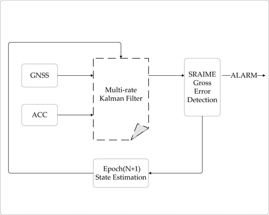
2.1. GNSS/Accelerometer Integration Algorithm Based on Kalman Filter

The slow-growing fault detection method of the GNSS/accelerometer integrated system for deformation monitoring was established based on Gaussian assumption and statistical hypothesis testing. Therefore, it is assumed that the state variable X n x has a known prior Gaussian probability density function (PDF),
p ( X ) = N { X ; X ¯ k , P X ¯ k }
where N { X ; X ¯ k , P X ¯ k } is a normal distribution with a mean of X ¯ k = E [ X ] and a covariance of P X ¯ k = cov [ X ] . Meanwhile, this state is obtained indirectly through the observation quantity Z n z in the observation equation,
Z = h ( X ) + V
where h ( X ) is a nonlinear function known from the set n x n z , V is the measurement noise in the probability density function p ( X ) = N { V ; 0 n z , R } . The state variable X is the unknown quantity, and the observation quantity Z is the known quantity.
According to Bayes’ theorem, the posterior estimate of the state vector can be calculated as,
p ( X | Z ) = p ( X , Z ) p ( Z ) = p ( Z | X ) p ( X ) p ( Z | X ) p ( X ) d X
where p ( Z | X ) is the only measurement probability density function associated with observation Equation (2), and δ represents the Dirac δ function,
p ( Z | X ) = δ ( Z h ( X ) V ) p ( X ) p ( V ) d X d V
The second-order Taylor expansion of the position of the carrier monitoring point with respect to time is a constant acceleration model, i.e., the position, velocity, and acceleration of the point, are regarded as state parameters. The third-order or higher-order Taylor expansion is regarded as the random disturbance of the acceleration rate of change, i.e., if the random disturbance of the acceleration rate of change is assumed to be 0, the dynamic system performs uniform acceleration motion. When the sampling interval is very small, other external disturbances are regarded as random disturbances, thus establishing a constant acceleration model.
It is simply assumed that the carrier moves uniformly in the Z-direction. Then, the state equation (Equation (5)) and observation equation (Equation (6)) of the filtering system can be expressed as:
[ X k X ˙ k X ¨ k ] = [ I Δ t I 1 2 Δ t 2 I 0 I Δ t I 0 0 I ] [ X k 1 X ˙ k 1 X ¨ k 1 ] + [ 0 0 I ] W k
Z k = [ L G P S L a c c ] = [ I 0 0 0 0 I ] [ X k X ˙ k X ¨ k ] + V k
where, X k represents displacement; X ˙ k represents velocity; X ¨ k represents acceleration, and W k is the excitation noise of the system.
The Kalman filter state equation and observation equation are established as,
          { X k + 1 = Φ k X k + G k W k                                               Z k + 1 = H k + 1 X k + 1 + V k + 1                                          
Assuming that W k is a steady-state white noise sequence, if the disturbance of acceleration is regarded as a random process and the disturbance of acceleration obeys the Gaussian white noise with an expectation of 0 and a covariance of δ 2 I , the unit of δ 2 is m 2 s 4 , then, according to the law of covariance propagation, the covariance of W k is:
Q k = Φ k [ 0 0 0 0 0 0 0 0 δ 2 I ] Φ k T = [ I Δ t I 1 2 Δ t 2 I 0 I Δ t I 0 0 I ] [ 0 0 0 0 0 0 0 0 δ 2 I ] [ I Δ t I 1 2 Δ t 2 I 0 I Δ t I 0 0 I ] T = δ 2 [ 1 4 Δ t 4 I 1 2 Δ t 3 I 1 2 Δ t 2 I 1 2 Δ t 3 I Δ t 2 I Δ t I 1 2 Δ t 2 I Δ t I I ]
Then, the time update process and measurement update process of the GNSS/accelerometer integrated system based on Kalman filtering are as follows:
      X ^ k = ( H k T P ¯ k H k + P X ¯ k ) 1 ( H k T P ¯ k Z k + P X ¯ k X ¯ k )
          K k = P X ¯ k H k T ( H k P X ¯ k H k T + R k ) 1
    P X k = ( I K k H k ) P X ¯ k ( I K k H k ) T + K k R k K k T
X ¯ k Φ k 1 X ^ k 1 N { X k 1 ; X ^ k 1 , P X k 1 } d X k 1
P X ¯ k ( Φ k 1 X ^ k 1 X ¯ k ) 2 N { X k 1 ; X ^ k 1 , P X k 1 } d X k 1 + G k 1 Q k 1 G k 1 T
    Z ^ k ' H k X ^ k N { X k ; X ^ k , P X k } d X k
    P Z ^ k ' ( H k X ^ k Z ^ k ' ) 2 N { X k ; X ^ k , P X k } d X k
In the formula, k represents time t k , and the observed variance coefficient matrix H k = [ I 0 0 0 0 I ] ; Φ k = [ I Δ t I 1 2 Δ t 2 I 0 I Δ t I 0 0 I ] is the system state transition matrix from time t k 1 to time t k ; G k 1 = [ 0 0 I ] is the noise driving matrix; the acceleration disturbance is regarded as Gaussian white noise whose covariance matrix is δ 2 I , and then the covariance matrix of W k is Q k 1 = δ 2 [ 1 4 Δ t 4 I 1 2 Δ t 3 I 1 2 Δ t 2 I 1 2 Δ t 3 I Δ t 2 I Δ t I 1 2 Δ t 2 I Δ t I I ] ; X ¯ k is the predicted value of the state parameter vector corresponding to time t k , and X ^ k is the estimated value of the state parameter at time t k ; K k is the gain matrix; P X k is the covariance matrix of the estimated value X ^ k of the state parameter, P X ¯ k is the covariance matrix of the predicted value X ¯ k of the state parameter, and P Z ^ k ' is the covariance matrix of the predicted observation value Z ^ k ' ; R k is the measurement noise covariance matrix; Δ t is the sampling rate.

2.2. Slow-Growing Gross Error Detection Algorithm Based on State Domain

This study used statistical hypothesis testing to detect gross errors in the deformation monitoring system, where the null hypothesis B 0 : means that the GNSS/ accelerometer fusion estimate X ^ k and its covariance matrix P X k have no error, and the alternative hypothesis B 1 : means that there is an error to test.
In the least squares method, the residual v i = Z i H i X ^ i conforms to a normal distribution, i.e., v i ~ N ( 0 , 1 ) . According to the definition of Chi-squared distribution, the distribution law of the variable composed of the sum of squares of k random variables that obey the normal distribution, i.e., the residual sum of squares i = 0 k v i 2 is called the Chi-squared distribution. The Chi-squared variable χ 2 is defined based on the sum of squared errors, and the Chi-squared increment Δ χ k 2 is sensitive to abnormal observations between two epochs and significant errors in the current epoch. The Chi-squared increment Δ χ k 2 is extended to the Kalman filter, and the Chi-squared variable χ k 2 based on the sum of squared errors from t 0 to t k is defined as:
    χ k 2 = i = 0 k v i 2 = i = 0 k ( Z i H i X ^ i ) T R i 1 ( Z i H i X ^ i )
The Chi-squared increment Δ χ k 2 at t k is defined as:
    Δ χ k 2 = χ k 2 χ k 1 2
Then, the recursive form of Δ χ k 2 can be obtained, where Δ X ^ k = X ^ k X ^ k 1 :
                                                                                                                                    Δ χ k 2 = Δ X ^ k T K k T P X k 1 1 K k Δ X ^ k                                                                                                       + ( Z k H k X ^ k ) T K k T R k 1 K k ( Z k H k X ^ k )
However, in practical applications, if the Δ χ k 2 derived from Equation (18) is used as the indicator of fault detection, once a slowly changing gross error occurs, it means that there are errors in the state estimation value X ^ k and its covariance matrix P X k at the next moment, and recursion cannot be performed to obtain the state estimation value at the next moment. Consequently, to ensure the accuracy of the Δ χ k 2 indicator, the estimated value of Δ χ k 2 must be obtained before the state update. This paper denotes Δ X ^ k and observation residuals at t k by the state predicted value X ¯ k :
Δ X ^ k = P X ¯ k H k T ( H k P X ¯ k H k T + R k ) 1 ( Z k H k X ¯ k )
Z k H k X ^ k = R k ( H k P X ¯ k H k T + R k ) 1 ( Z k H k X ¯ k )
Substituting Equations (19) and (20) into Equation (18) yields:
    Δ χ k 2 = ( Z k H k X ¯ k ) T K k T ( P X k P X ¯ k ) 1 K k ( Z k H k X ¯ k )
Meanwhile, it can be obtained by the Kalman filter:
X ^ k X ¯ k = K k ( Z k H k X ¯ k )
Let the difference between the estimated value X ^ k and the state predicted value X ¯ k be d k , Then, under the condition that the null hypothesis B 0 holds, d k should obey the Gaussian white noise release with a mathematical expectation of 0, namely:
    d k = X ^ k X ¯ k = K k ( Z k H k X ¯ k )
Its variance is:
P d k = P X k P X ¯ k = K k P Z ^ k ' K k T = K k ( H k P X ¯ k H k T + R k ) K k T
Formula (18) can be simplified as:
Δ χ k 2 = d k T P d k 1 d k ,   Δ χ k 2 ~ p ( Δ χ k 2 )
Equations (25) and (17) are the sums of squared residuals, If the null hypothesis B 0 holds, the probability density function p ( Δ χ k 2 ) approximately conforms to a Chi-squared distribution with n x degrees of freedom, where n x is the dimension of the state domain.
According to the above derivation and the recurrence principle and information distribution principle in AIME, it can be seen that the proposed method differs from the AIME method in that it performs gross error detection in the state domain, and the test statistic is constructed directly by using the prior information and the posterior information, without considering the dimension of the observation matrix.
The specific steps of the slow-growing gross error detection algorithm for GNSS/accelerometer integrated bridge deformation monitoring in the state domain are as follows:
1.
Determine the false alarm rate P F A according to the bridge monitoring environment;
2.
Obtain the estimated value X ^ k of epoch k and its covariance matrix P X k through GNSS/accelerometer fusion Kalman filter;
3.
Determine the recurrence period m . Assuming that epoch k m has no faults, the multi-step extrapolation estimated value X ¯ k s and its covariance matrix P X ¯ k s from epoch k m to epoch k can be obtained by calculating the estimated value X ^ k m of epoch k-m and its covariance matrix P X k m :
    X ¯ k s = i = 1 m Φ ( k m + i , k m + 1 ) X ^ k m
      P X ¯ k s = i = 1 m Φ ( k m + i , k m + 1 ) P X k m Φ ( k m + i , k m + 1 ) T + G k m Q k m G k m T
4.
Calculate d k and its covariance matrix P d k :
          d k m + i = X ^ k m + i X ¯ k m + i s
P d k m + i = P X k m + i P X ¯ k m + i s
5.
Construct the slow-growing fault detection statistic Δ χ a v g , k 2 in the state domain, where singular value decomposition is used when inverting P d k m + i to increase the calculation stability:
        Δ χ a v g , k 2 = d a v g , k T P d a v g , k 1 d a v g , k
d a v g , k = ( P d a v g , k 1 ) 1 ( i = 1 m P d k m + i ) 1 d k m + i
P d a v g , k 1 = i = 1 m P d k m + i
6.
Calculate the fault detection threshold under the false alarm rate P F A , where F ( Δ χ a v g , k 2 ) is the cumulative distribution function of p ( Δ χ a v g , k 2 ) , the operator inf represents the lower bound, and T F A , k Z is the fault detection threshold,
      T F A , k Z = inf ( Δ χ a v g , k 2 : ( 1 P F A ) F ( Δ χ a v g , k 2 ) )
7.
Compare the state test statistic Δ χ a v g , k 2 ( 30 ) with the threshold T F A , k Z ( 33 ) : If Δ χ a v g , k 2 T F A , k Z , it is considered that there is no fault and no slow-growing gross error; if Δ χ a v g , k 2 > T F A , k Z , it is considered that there is a slow-growing fault and a slow-growing gross error.
Based on the state domain consistency theory, the GNSS/accelerometer integrated deformation monitoring method is proposed for slow-varying gross error detection. The specific detection process is shown in Figure 1:

3. Experiments and Discussion

In this paper, two sets of measured data were used in experiments. In the process of experimental verification, the GNSS observation data was post-processed by dynamic relative positioning, and the processed GNSS displacement and accelerometer raw data were used as input values. Then, the slope linear gross error was added to the measurement, and the proposed SRAIME method and the traditional AIME method were adopted to identify the gross error. Finally, the identification results of the two methods were compared to verify the effectiveness and reliability of the proposed SRAIME method.

3.1. Analysis of Experimental Results of Anhui Suntuan River Bridge

In Experiment 1, the Anhui Suntuan River Bridge was taken as the object. The bridge has a total length of 358 m, of which the main span is a 112-m tied arch bridge. The main bridge is 16.5 m wide, and the deck is 9 m wide. During the experiment, a GNSS/accelerometer integrated machine and a SPAN-IGM-A1 inertial unit were installed at the monitoring station at the main span of the bridge, and the sampling rates were 10 Hz and 200 Hz, respectively; a Trimble R10 GNSS receiver was installed at the reference station with a sampling rate of 10 Hz. The experimental scene and device are presented in Figure 2.
For experimental verification, the GNSS displacement and the raw data of the accelerometer in the U direction were used as input values. In the measurement domain, the slope slow-growing gross error was added, and the fusion process before and after adding the gross error was detected by AIME and SRAIME, which can verify the effectiveness and reliability of SRAIME for GNSS/accelerometer integrated deformation monitoring. During the experiment, the false alarm rate was set to 10 1 , the m was set to 5.
Figure 3 shows the vertical GNSS displacement and the raw data of the accelerometer for 300 s. The two types of data were fused to overcome the disadvantage of the low GNSS sampling rate. Figure 4 shows the comparison of the results before and after GNSS/accelerometer fusion. The red part represents the vertical displacement after fusion, where the accuracy was improved. Figure 5a,b illustrate the detection statistics and gross error alarms obtained by the AIME method and SRAIME method respectively. It can be seen that the results obtained by the two methods were consistent, the detection statistics without gross errors were all smaller than the set threshold, and no alarm was issued. This result verified the equivalence of the proposed SRAIME method and the traditional AIME method.
To verify the effectiveness of the proposed method, a slow-change gross error of 0.0003 × (k − 20) ns/s was added in the state update process from 110 s to 150 s. In Figure 6, the fusion displacement after adding the gross error is illustrated, and the slowly-growing gross error can be observed from 110 s to 150 s, which was consistent with the simulation situation. Meanwhile, the SRAIME method and the AIME method were respectively applied to identify gross errors in this process, and the results are presented in Figure 7. Figure 7a shows the state detection statistics obtained during the fusion process, and the detection statistics obtained by the two methods corresponding to adding the gross error part were both greater than the threshold; Figure 7b shows the alarm situation. From 110 s to 150 s, both methods issued an alarm, indicating that they can effectively identify the slow-growing gross errors in the state domain and issue an alarm, which further verified the equivalence of the two methods.
To further compare the two methods, Table 1 presented the time when the two methods first issued an alarm and the corresponding detection statistics. It can be seen that the first alarm time and detection statistics of the two methods are completely consistent. However, according to the theoretical derivation in Section 3, the proposed SRAIME method does not need to reconstruct the innovation in the recursive process of gross error detection, and it does not need to consider the dimensional change of the observation matrix in the fusion process, thus further improving the universality and efficiency of gross error detection.

3.2. Analysis of Experimental Results of Wilford Bridge, UK

In Experiment 2, the Wilford Bridge in England was taken as the object, which is a suspension pedestrian bridge over the Trent River in Nottingham, England. The bridge is 69 m long and 3.7 m wide, and it is supported by two sets of suspension cables and restrained by two boulder anchors. The steel deck of the bridge deck is covered by a layer of wooden slats.
In this experiment, a Lecia SR530 dual-frequency receiver equipped with a Kistler K-BEAM 8392A2 three-axis accelerometer was installed in the bridge’s mid-span, and the sampling rate of the accelerometer and the GNSS receiver was 80 Hz and 10 Hz, respectively. Meanwhile, the two Lecia SR530 receivers installed in Figure 8 were used as reference stations, and the experimental scene and device are shown in Figure 9. In Figure 9, the upper side is the GNSS antenna, and the lower side is the accelerometer device. During the monitoring process, the bridge was excited to deform by crowds running and jum** on the bridge, and each excitation lasted for two minutes, including 20 s of active excitation and damped free oscillation. Table 2 lists the selected seven experimental events, and the specific experimental descriptions are presented in Table 2. The experimental verification method was consistent with that introduced in Section 3.1, where the false alarm rate was also set to 10 1 and the m was set to 5.
Experiment 2 used the GNSS/accelerometer data at the mid-span of the Wilford Bridge for 1800 s. The upper picture in Figure 10 shows the U-direction deformation of the bridge and the original accelerometer observation data obtained after the relative positioning of the GNSS observation data, where the corresponding experimental events are marked in the acceleration data. Since the completed events were all high-frequency vibrations, the deformation caused by them was not reflected in the GNSS displacement. The blue part in Figure 11 represents the GNSS vertical displacement before fusion, and the red post-fusion displacement combines the low-frequency deformation of the GNSS vertical displacement and the high-frequency deformation of the accelerometer raw data, which fully combined the advantages of the two sensors. During the fusion process, the traditional AIME method and the proposed SRAIME method were adopted for slow-growing gross error detection. Figure 12 shows the gross error detection results of AIME and SRAIME, where Figure 12a shows the gross error detection statistics, and Figure 12b shows the gross error alarm condition. Among them, Event 1\2\6\7 encompassed jum** in the middle span of the bridge, causing violent oscillation, which was consistent with the form of abrupt gross error. Thus, the detection statistics of the two methods in Figure 12 at the event exceeded the set threshold, and an alarm was issued. However, Event 3\4\5 encompassed running normally, which conformed to the normal posture of the bridge deformation, so no alarm was issued. Additionally, there was an alarm near 50 s in Figure 12, which corresponded to the spur at the vertical displacement of the GNSS, indicating that there was a large gross error in the displacement of the GNSS. In the process of GNSS/accelerometer fusion, the AIME method and the proposed SRAIME method obtained consistent results, and both can detect slow-growing gross errors. The SRAIME method does not need to consider the dimension of the observation matrix, indicating that it has better generality and suitability in the fusion system.
In this experiment, the deformation caused by some events was similar to the gross error of mutation. To further verify the effectiveness of the proposed method, a slow-growing error was added artificially between 600 s and 700 s in the measurement domain. Figure 13 shows the vertical displacement after GNSS/accelerometer fusion after adding gross errors, and an obvious slow-growing fault gross between 600 s and 700 s. Then, the AIME method and the proposed SRAIME method were adopted for gross error detection, and the detection results are presented in Figure 14. Figure 14a shows the slow-varying gross error detection statistics obtained by the two methods after adding gross errors, and the detection statistics between 600 s and 700 s all exceeded the set threshold; Figure 14b shows the gross error alarms of the two methods after adding gross errors, both of which issued an alarm between 600 s and 700 s, indicating that the two methods have the same detection performance for slow-growing gross errors. Table 3 presents the first alarm time, first alarm detection statistics, and alarm threshold of the AIME method and the SRAIME method between 600 s and 700 s. Consistent with the observation obtained in Section 3.1, the proposed SRAIME method obtained consistent results with the AIME method, but SRAIME does not need to consider the dimension change of the observation matrix during the fusion process.

4. Conclusions

This paper proposes a slow-growing gross error detection method called SRAIME for GNSS/accelerometer integrated deformation monitoring based on state domain consistency theory. The proposed SRAIME method does not need to reconstruct the innovation in the recursive process, which greatly improves the fault detection efficiency. Meanwhile, because the change of the dimension of the observation matrix in the fusion process does not need to be considered, the calculation difficulty is reduced.
To verify the effectiveness of the SRAIME method, this paper used the theoretical derivation and GNSS/accelerometer fusion system to monitor the deformation of the Suntuan River Bridge in Anhui and the Wilford Bridge in the UK. When the GNSS/accelerometer was fused, dynamic relative positioning post-processing was performed on the GNSS observation data, and the obtained high-precision GNSS vertical displacement and acceleration raw data were used as inputs for fusion. Meanwhile, the traditional AIME method and the proposed SRAIME were adopted to detect gross errors in the GNSS/acceleration fusion process. Then, to further verify the effectiveness of the method, the slow-growing gross error of the slope was added to the specified period in the measurement domain. In the two groups of experiments, the AIME method and the proposed SRAIME method obtained consistent results. This indicated that the SRAIME method can correctly and effectively identify slow-growing gross errors of the fusion monitoring system, demonstrating the effectiveness and reliability of the method in structural deformation monitoring by GNSS/accelerometer fusion.
To adapt to the diversity and complexity of bridge deformation monitoring environment, multi-sensor fusion has been widely used. However, when multi-sensors are integrated into deformation monitoring, the problem of system gross errors is often encountered. The method proposed in this paper is only limited to gross error detection and lacks the key part of gross error exclusion. Therefore, eliminating the detected gross errors will be explored in future work.

Author Contributions

A.S. processed data, and wrote the manuscript; Q.Z. and Z.Y. provided the initial idea and designed the research; X.M. provided raw data; X.L. and Y.Z. helped to accomplish some tests; Q.Z., X.M. and Y.X. helped with the writing. All authors have read and agreed to the published version of the manuscript.

Funding

This manuscript is supported by National Engineering Laboratory for Digital Construction and Evaluation Technology of Urban Rail Transit (No. 2021ZH03), the National Natural Science Foundation of China (No. 42074226), the Natural Science Foundation of Jiangsu Province (No. BK20221146) and the China Postdoctoral Science Foundation (No. 2021M703496).

Data Availability Statement

Not applicable.

Acknowledgments

ESA is acknowledged for sponsoring the GeoSHM projects.

Conflicts of Interest

The authors declare no conflict of interest.

References

  1. Yu, J.; Meng, X.; Yan, B.; Xu, B.; Fan, Q.; **e, Y. Global Navigation Satellite System-based Positioning Technology for Structural Health Monitoring: A Review. Struct. Control Health Monit. 2020, 27, e2467. [Google Scholar] [CrossRef]
  2. Yang, Y.; Ding, Q.; Gao, W.; Li, J.; Xu, Y.; Sun, B. Principle and Performance of BDSBAS and PPP-B2b of BDS-3. Satell. Navig. 2022, 3, 5. [Google Scholar] [CrossRef]
  3. Yu, J.Y.; Shao, X.D.; Meng, X.L.; Li, L.F. Experimental research on dynamic monitoring of bridges using gnss and accelerometer. China J. Highw. Transp. 2014, 27, 62–69. [Google Scholar]
  4. Yang, Y.; Mao, Y.; Sun, B. Basic Performance and Future Developments of BeiDou Global Navigation Satellite System. Satell. Navig. 2020, 1, 1–8. [Google Scholar] [CrossRef]
  5. Tolman, B.W.; Craig, B.K. An integrated GPS/accelerometer system for low dynamics applications. In Proceedings of the International Symposium on Kinematic Systems in Geodesy, Geomatics, and Navigation, Banff, AB, Canada, 5–8 June 2001; pp. 151–159. [Google Scholar]
  6. Li, X.; Ge, L.; Ambikairajah, E.; Rizos, C.; Tamura, Y.; Yoshida, A. Full-Scale Structural Monitoring Using an Integrated GPS and Accelerometer System. Gps Solut. 2006, 10, 233–247. [Google Scholar] [CrossRef]
  7. Chan, W.S.; Xu, Y.L.; Ding, X.L.; Dai, W.J. An Integrated GPS-Accelerometer Data Processing Technique for Structural Deformation Monitoring. J. Geod. 2006, 80, 705–719. [Google Scholar] [CrossRef]
  8. Dai, W.J.; Wu, X.X.; Luo, F.Y. Integration of GPS and accelerometer for high building vibration monitoring. J. Vib. Shock. 2011, 30, 223–226, 249. [Google Scholar]
  9. Moschas, F.; Stiros, S. Measurement of the Dynamic Displacements and of the Modal Frequencies of a Short-Span Pedestrian Bridge Using GPS and an Accelerometer. Eng. Struct. 2011, 33, 10–17. [Google Scholar] [CrossRef]
  10. Han, H.Z.; Wang, J.; Meng, X.L. Reconstruction of bridge dynamics using integrated GPS and accelerometer. J. China Univ. Min. Technol. 2015, 44, 549–556. [Google Scholar]
  11. Xu, Y.; Brownjohn, J.M.W.; Hester, D.; Koo, K.Y. Long-Span Bridges: Enhanced Data Fusion of GPS Displacement and Deck Accelerations. Eng. Struct. 2017, 147, 639–651. [Google Scholar] [CrossRef]
  12. Kim, K.; Choi, J.; Chung, J.; Koo, G.; Bae, I.-H.; Sohn, H. Structural Displacement Estimation through Multi-Rate Fusion of Accelerometer and RTK-GPS Displacement and Velocity Measurements. Measurement 2018, 130, 223–235. [Google Scholar] [CrossRef]
  13. Hou, H.; Kuang, C.; Zhou, Y.; Zhang, Y. Feasibility Study of Low Cost Receiver for Deformation Monitoring. In China Satellite Navigation Conference (CSNC) 2018 Proceedings; Lecture Notes in Electrical Engineering; Sun, J., Yang, C., Guo, S., Eds.; Springer: Singapore, 2018; Volume 497, pp. 129–138. ISBN 9789811300042. [Google Scholar]
  14. Notti, D.; Cina, A.; Manzino, A.; Colombo, A.; Bendea, I.H.; Mollo, P.; Giordan, D. Low-Cost GNSS Solution for Continuous Monitoring of Slope Instabilities Applied to Madonna Del Sasso Sanctuary (NW Italy). Sensors 2020, 20, 289. [Google Scholar] [CrossRef] [PubMed]
  15. Tu, R.; Wang, R.; Ge, M.; Walter, T.R.; Ramatschi, M.; Milkereit, C.; Bindi, D.; Dahm, T. Cost-effective Monitoring of Ground Motion Related to Earthquakes, Landslides, or Volcanic Activity by Joint Use of a Single-frequency GPS and a MEMS Accelerometer. Geophys. Res. Lett. 2013, 40, 3825–3829. [Google Scholar] [CrossRef] [Green Version]
  16. Tu, R.; Liu, J.; Zhang, R.; Fan, L.; Han, J. Real-Time Kinematic Positioning Algorithm with GNSS and High-Frequency Accelerometer Observations for Broadband Signals. Meas. Sci. Technol. 2019, 31, 035007. [Google Scholar] [CrossRef]
  17. Sun, K.T.; Gao, Y.; Wu, X.D. Application of MEMS Sensors in Abnormal Deformation Monitoring of Metro Tunnel Structure. In Proceedings of the International Conference on Smart Transportation and City Engineering 2021; Li, Z., Chen, X., Yan, K., Cen, F., Peng, L., Lin, N., Eds.; SPIE: Chongqing, China, 2021; p. 75. [Google Scholar]
  18. Lăpădat, A.M.; Tiberius, C.C.J.M.; Teunissen, P.J.G. Experimental Evaluation of Smartphone Accelerometer and Low-Cost Dual Frequency GNSS Sensors for Deformation Monitoring. Sensors 2021, 21, 7946. [Google Scholar] [CrossRef] [PubMed]
  19. Smyth, A.; Wu, M. Multi-Rate Kalman Filtering for the Data Fusion of Displacement and Acceleration Response Measurements in Dynamic System Monitoring. Mech. Syst. Signal Process. 2007, 21, 706–723. [Google Scholar] [CrossRef]
  20. Kogan, M.G.; Kim, W.-Y.; Bock, Y.; Smyth, A.W. Load Response on a Large Suspension Bridge during the NYC Marathon Revealed by GPS and Accelerometers. Seismol. Res. Lett. 2008, 79, 12–19. [Google Scholar] [CrossRef]
  21. Chang, C.C.; **ao, X.H. An Integrated Visual-Inertial Technique for Structural Displacement and Velocity Measurement. Smart Struct. Syst. 2010, 6, 1025–1039. [Google Scholar] [CrossRef]
  22. Lai, T.; Ting-Hua, Y.I.; Wang, J.Y.; Lin, Y.X.; Hong-Nan, L.I. Data Fusion of Displacement and Acceleration Measurements Based on Multi-rate Kalman Filtering Technique. J. Disaster Prev. Mitig. Eng. 2012, 32, 707–713. [Google Scholar]
  23. Meng, X.; Wang, J.; Han, H. Optimal GPS/Accelerometer Integration Algorithm for Monitoring the Vertical Structural Dynamics. J. Appl. Geod. 2014, 8, 265–272. [Google Scholar] [CrossRef]
  24. Yang, A.; Wang, P.; Yang, H. Bridge Dynamic Displacement Monitoring Using Adaptive Data Fusion of GNSS and Accelerometer Measurements. IEEE Sens. J. 2021, 21, 24359–24370. [Google Scholar] [CrossRef]
  25. Han, H.; Wang, J.; Meng, X.; Liu, H. Analysis of the Dynamic Response of a Long Span Bridge Using GPS/Accelerometer/Anemometer under Typhoon Loading. Eng. Struct. 2016, 122, 238–250. [Google Scholar] [CrossRef]
  26. Hide, C.; Moore, T.; Smith, M. Adaptive Kalman Filtering for Low-Cost INS/GPS. J. Navig. 2003, 56, 143–152. [Google Scholar] [CrossRef]
  27. Li, X.; Wang, H.; Li, S.; Feng, S.; Wang, X.; Liao, J. GIL: A Tightly Coupled GNSS PPP/INS/LiDAR Method for Precise Vehicle Navigation. Satell. Navig. 2021, 2, 26. [Google Scholar] [CrossRef]
  28. Teunissen, P.; Salzmann, M. A Recursive Slippage Test for Use in State-Space Filtering. Manuscr. Geod. 1989, 14, 383–390. [Google Scholar]
  29. Brumback, B.; Srinath, M. A Chi-Square Test for Fault-Detection in Kalman Filters. IEEE Trans. Autom. Control 1987, 32, 552–554. [Google Scholar] [CrossRef]
  30. Li, P. Investigation of System Fault Detectionin INS/GNSS/SAR Integrated Navigation System. J. Proj. Rocket. Missiles Guid. 2005, 7, 309–312. [Google Scholar]
  31. Li, T.; Zhou, J.B.; Liu, Y.P. Federal Kalman Filter Based on Residual Chi-Square Test Method. Aerosp. Control. 2017, 35, 56–59. [Google Scholar]
  32. **ong, H.; Bian, R.; Li, Y.; Du, Z.; Mai, Z. Fault-Tolerant GNSS/SINS/DVL/CNS Integrated Navigation and Positioning Mechanism Based on Adaptive Information Sharing Factors. IEEE Syst. J. 2020, 14, 3744–3754. [Google Scholar] [CrossRef]
  33. Bar-Shalom, Y.; Kirubarajan, T.; Li, X.R. Estimation with Applications to Tracking and Navigation; Wiley-Interscience: Hoboken, NJ, USA, 2001. [Google Scholar]
  34. Li, X.R.; Zhao, Z. Evaluation of Estimation Algorithms. Part 1: Incomprehensive Measures of Performance. IEEE Trans. Aerosp. Electron. Syst. 2006, 42, 1340–1358. [Google Scholar] [CrossRef]
  35. Chun, Y.; Lei, Z.; Jian, G.; Qingwei, C. Fault-tolerant integrated navigation algorithm using chi-square test with two state propagators and fuzzy adaptive filter. Control. Theory Appl. 2016, 33, 500–511. [Google Scholar]
  36. Diesel, J.; Dunn, G. GPS/IRS AIME: Certification for Sole Means and Solution to RF Interference. In Proceedings of the Proceedings of the 9th International Technical Meeting of the Satellite Division of The Institute of Navigation (ION GPS 1996), Kansas City, MO, USA, 17–20 September 1996; pp. 1599–1606. [Google Scholar]
  37. Liu, H.Y.; Feng, C.T.; Wang, H.N. Method of Inertial Aided Satellite Navigation and Its Integrity Monitoring. J. Astronaut. 2011, 32, 775–780. [Google Scholar]
  38. Zhong, L.N.; Liu, J.Y.; Li, R.B.; Wang, R. Approach for detection of slowly growing errors in INS/GNSS tightly-coupled system based on LS-SVM. J. Chin. Inert. Technol. 2012, 20, 754–758. [Google Scholar]
  39. Bhatti, U.I.; Ochieng, W.Y.; Feng, S. Performance of Rate Detector Algorithms for an Integrated GPS/INS System in the Presence of Slowly Growing Error. GPS Solut. 2012, 16, 293–301. [Google Scholar] [CrossRef]
  40. Li, X.; Zhao, X.; Pang, C.; He, Z. Integrity Monitoring of Integrated GNSS /SINS System Based on PBN. Electron. Opt. Control. 2013, 20, 44–48. [Google Scholar]
  41. Zhao, X.; Gao, C.; Pang, C.; Zhang, C.; Wang, Y. A double-threshold test method for soft faults assisted by BP neural network. Control. Decrsion 2020, 35, 1384–1390. [Google Scholar]
Figure 1. The flow chart of the GNSS/accelerometer integrated deformation monitoring method for slow-growing fault detection in the state domain.
Remotesensing 14 04758 g001
Figure 2. Monitoring site and device: (a) Suntuan River Bridge; (b) monitoring station.
Remotesensing 14 04758 g002
Figure 3. Suntuan River Bridge vertical GNSS displacement and acceleration.
Remotesensing 14 04758 g003
Figure 4. Suntuan River Bridge vertical displacement before and after GNSS/acceleration fusion.
Remotesensing 14 04758 g004
Figure 5. Suntuan River Bridge slow-varying gross error detection results by GNSS/accelerometer fusion: (a) Gross error detection statistics; (b) Gross error detection alarm condition.
Remotesensing 14 04758 g005
Figure 6. Suntuan River Bridge vertical displacement of GNSS/accelerometer fusion after adding gross errors.
Remotesensing 14 04758 g006
Figure 7. The slowly-growing gross error detection result of Suntuan River Bridge by GNSS/accelerometer fusion after adding gross errors: (a) Detection statistics after adding gross errors; (b) Alert situation after adding gross errors.
Remotesensing 14 04758 g007
Figure 8. Wilford Bridge, Nottingham, UK.
Remotesensing 14 04758 g008
Figure 9. The Wilford Bridge test site with accelerometer setup.
Remotesensing 14 04758 g009
Figure 10. Wilford Bridge vertical GNSS displacement and acceleration.
Remotesensing 14 04758 g010
Figure 11. Wilford Bridge vertical displacement before and after GNSS/accelerometer fusion.
Remotesensing 14 04758 g011
Figure 12. The slow-growing gross error detection results of Wilford Bridge by GNSS/accelerometer fusion: (a) Gross error detection statistics; (b) Gross error detection alarm condition.
Remotesensing 14 04758 g012
Figure 13. Wilford Bridge vertical displacement of GNSS/accelerometer fusion after adding gross errors.
Remotesensing 14 04758 g013
Figure 14. The slowly-growing gross error detection results of Wilford Bridge by GNSS/accelerometer fusion after adding gross errors: (a) Detection statistics after adding gross errors; (b) Alert situation after adding gross errors.
Remotesensing 14 04758 g014
Table 1. Suntuan River Bridge statistics of AIME/SRAIME gross error detection results.
First Alarm Time/Detection StatisticsAlert Threshold
AIME110 s/4.634.24
SRAIME110 s/4.634.24
Table 2. Incentive bridge deformation events.
Experimental EventEvent Description
Event 130 people jumped at the midspan of the bridge, with a total weight of 2353 kg.
Event 230 people jumped at the midspan of the bridge, then 15 people left.
Event 3A column of 15 people ran from east to west to the middle span of the bridge, with a total weight of 1253 kg.
Event 4Located on the south side of the bridge, 15 people ran in a row from west to east.
Event 5Located in the northwest of the bridge,
15 people lined up to run from west to east.
Event 615 people jump on the bridge midspan.
Event 715 people jump on the bridge midspan.
Table 3. Wilford Bridge Statistics of AIME/SRAIME gross error detection results.
First Alarm Time/Detection StatisticsAlert Threshold
AIME600 s/5.075.05
SRAIME600 s/5.075.05
Publisher’s Note: MDPI stays neutral with regard to jurisdictional claims in published maps and institutional affiliations.

