1. Introduction
Liquid crystals (LCs) are one of the most widely-used materials in active and passive elements for changing a light wave’s properties. In particular, intensity, phase and polarization may all be modified by changing the LC director profile, the spatial orientation map of the optic axis. In active devices such as LC-based spatial light modulators and displays, the director profile is usually controlled by an applied voltage, which may have spatial variation depending on the application. In these cases, the surface alignment of the LC is typically simple, often uniform over relatively large areas, and the desired director profile can be realized by patterned electrodes. Conversely, geometric-phase holograms (GPHs) based on LCs [
1,
2,
3] have an in-plane optic axis that varies spatially, often with much higher resolution than typical display pixel sizes. At least so far, GPHs are nearly always fixed orientation profiles, which may be either a passive LC polymer network film or an active LC layer whose effective retardation may be adjusted by an applied electric field. Examples of such elements are polarization gratings (PGs) [
4,
5], geometric-phase lenses [
3], q-plates [
6], beam sha** elements [
7], apodizing phase plates [
8] and mechanical actuators [
9]. In this work, we focus both on the optical properties of these holograms and the challenges of high resolution spatial patterning in order to realize them.
2. Background
Traditional phase-only refractive and diffractive optics operate via the principle of changing the optical path length, either by modifying the refractive index or optical element thickness or both, sometimes called the dynamic phase. GPHs, however, operate via a completely different principle, the geometric phase. In LC-based GPHs, the spatially-varying in-plane optic axis orientation
of the LC (i.e., the director field) is equal to one half the phase shift
applied to the light wave’s phase (
), sometimes called the Pancharatnam–Berry effect [
10,
11].
Unlike traditional surface alignment techniques such as rubbing polyimide [
12], photo-alignment layers (PAL) [
13,
14] can fairly easily realize arbitrary, stable and high resolution surface alignment patterns. In these materials, a polymer is exposed to linearly-polarized light, usually UV, which causes isomerization [
15,
16], or some other molecular change, which creates a preferred alignment direction for LC that is applied subsequently. The desired orientation profiles can be realized by polarization holography [
1,
17,
18], digital micro-mirror devices (DMDs) [
19,
20], plasmonic metamasks (PMMs) [
21] and direct-write laser scanning [
22]. While polarization holography (an interferometric method) can generate nanoscale periodic patterns [
4], it cannot easily record arbitrary patterns. Notably, direct-write laser scanning stands out for the ability to record arbitrary patterns with easily adjustable pixel size, pixel number and element area. Our system currently can scan up to 200 × 200 mm
2. The flexibility and precise polarization control make it ideal for recording complex patterns, such as lenses [
23], q-plates, vector apodizing phase plates [
8] and Fourier/Fresnel holograms [
24].
Traditional computer-generated Fourier Transform holograms [
25,
26] are designed by retrieving the phase or amplitude profile on the hologram plane using certain algorithms [
27]. This retrieved phase is traditionally assumed to arise via the dynamic phase, which is inherently wavelength dependent. Therefore, this kind of hologram can only reconstruct the image perfectly for a single wavelength, and chromatic distortion will occur for a different illumination wavelength. The geometric phase [
10,
11] is the phase shift acquired from changes in polarization, often conveniently considered on the Poincaré sphere. The accumulated geometric phase is path dependent and thus can be modulated by a phase retarder with an optic axis orientation profile. Because of this, the geometric phase is wavelength independent and polarization sensitive. This fundamental difference from the dynamic phase leads to very different properties of GPHs. While we employ LCs here, note that GPHs have been realized by digital holography [
28] and metasurfaces (e.g., [
29,
30]), and a similar basic behavior has been verified.
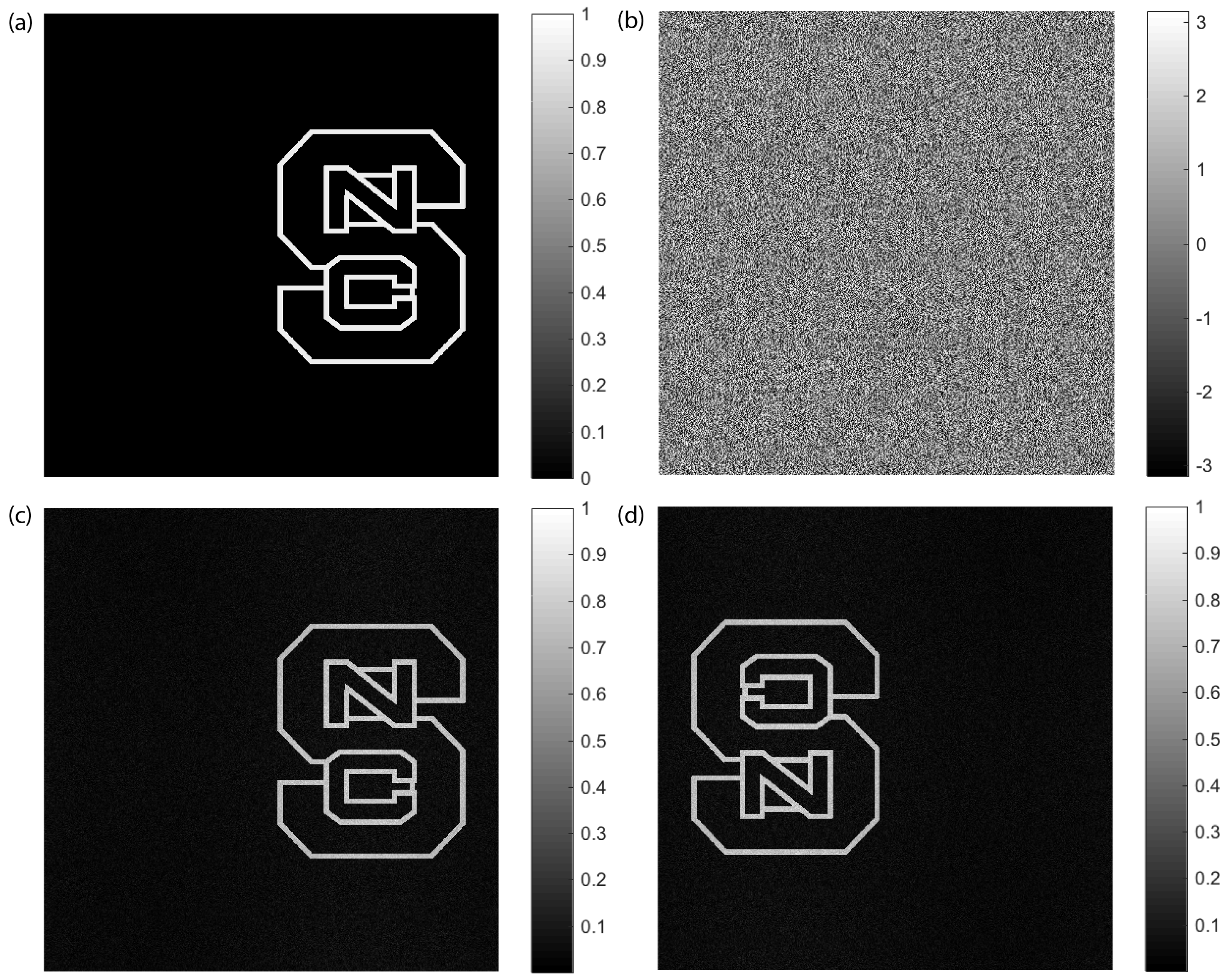
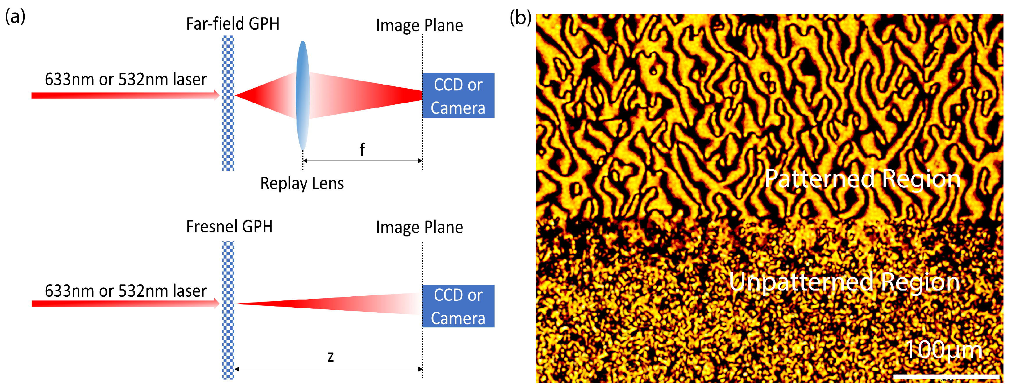
Here, we experimentally study computer-generated GPHs via photo-aligned LCs. To obtain a complete understanding of their diffraction properties, both far-field and Fresnel holograms are demonstrated. The phase pattern of the hologram is created by an iterative phase retrieval algorithm [
31] and recorded by the direct-write system [
22]. We examined the wavelength and polarization dependence and the effects of different recording pixel sizes.
4. Discussion
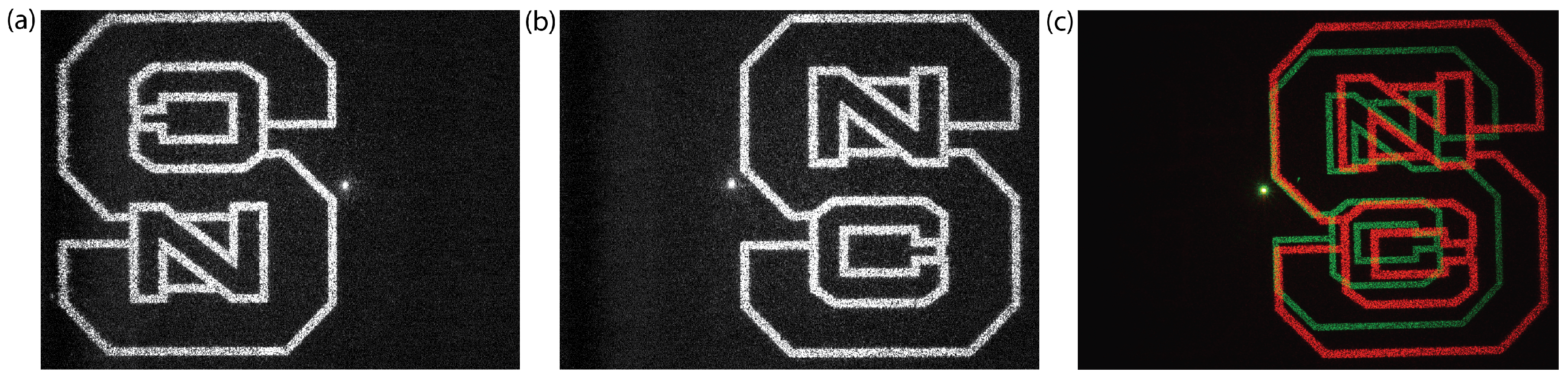
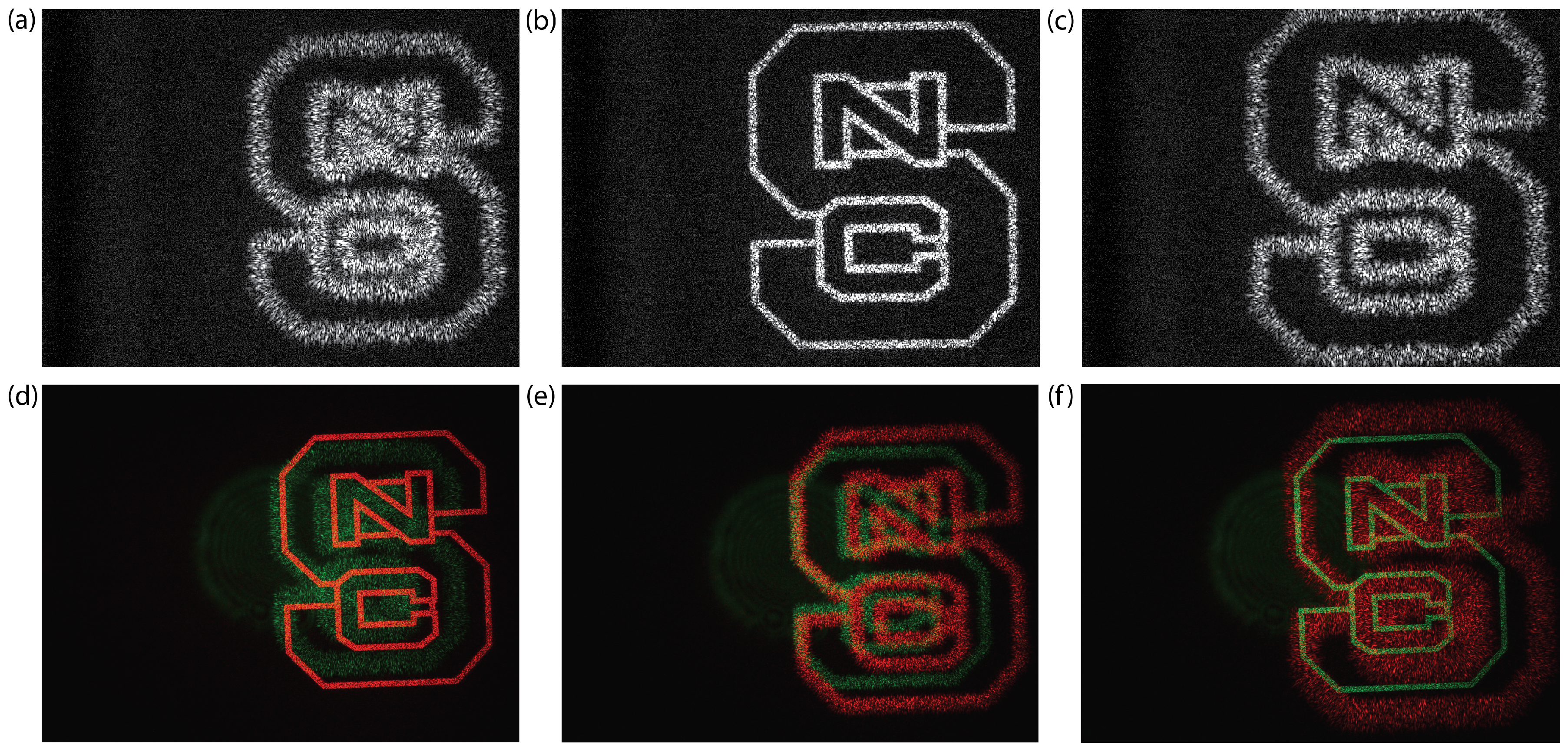
There is no noticeable scattering observed from the film. The noise observed from the replay images is mainly caused by conventional laser speckle and perhaps, to a much lesser extent, to imperfections in the phase recording. Localized defects between neighbor pixels have no significant effects on the image quality, but may lead to higher leakage. Since the leakage at the desired wavelength is about
, we conclude that alignment quality is generally good and within our expectation. Note that for both fabricated far-field and Fresnel geometric phase holograms, the zero order leakage is higher for green light since the film thickness is optimized for 633 nm. The broadband efficiency can be significantly improved when specific coating is applied, as shown in prior work [
32].
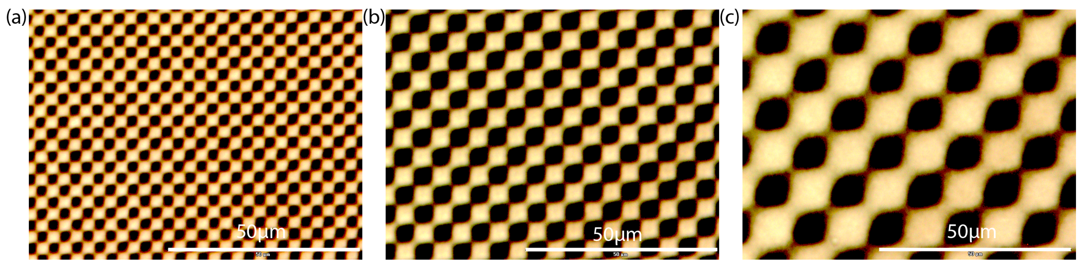
The maximum pattern area for our direct-write system is limited primarily by the size of the range and acceleration of the translation stage. The total number of pixels can vary depending on the pattern and spot size. For typical discrete patterns such as a checkerboard or a hologram, we can record more than four billion pixels that can be patterned with a 3-μm pixel size. Most of the patterns we record are not pixelated at all, but instead are continuous: neighboring scans are overlapped so that the average of the exposing polarizations is recorded. In this way, we can directly scan polarization gratings with periods down to about 3 μm and achieve point defects and disclination lines between boundaries of around 1 μm in width.
With the wavelength independent geometric phase, the fidelity of replay images is preserved perfectly for different wavelengths, but a spatial offset or magnification factor nevertheless remains due to chromatic dispersion. It may be possible to realize a fully-broadband and active holographic display if both the geometric and dynamic phases are controlled simultaneously.
5. Materials and Methods
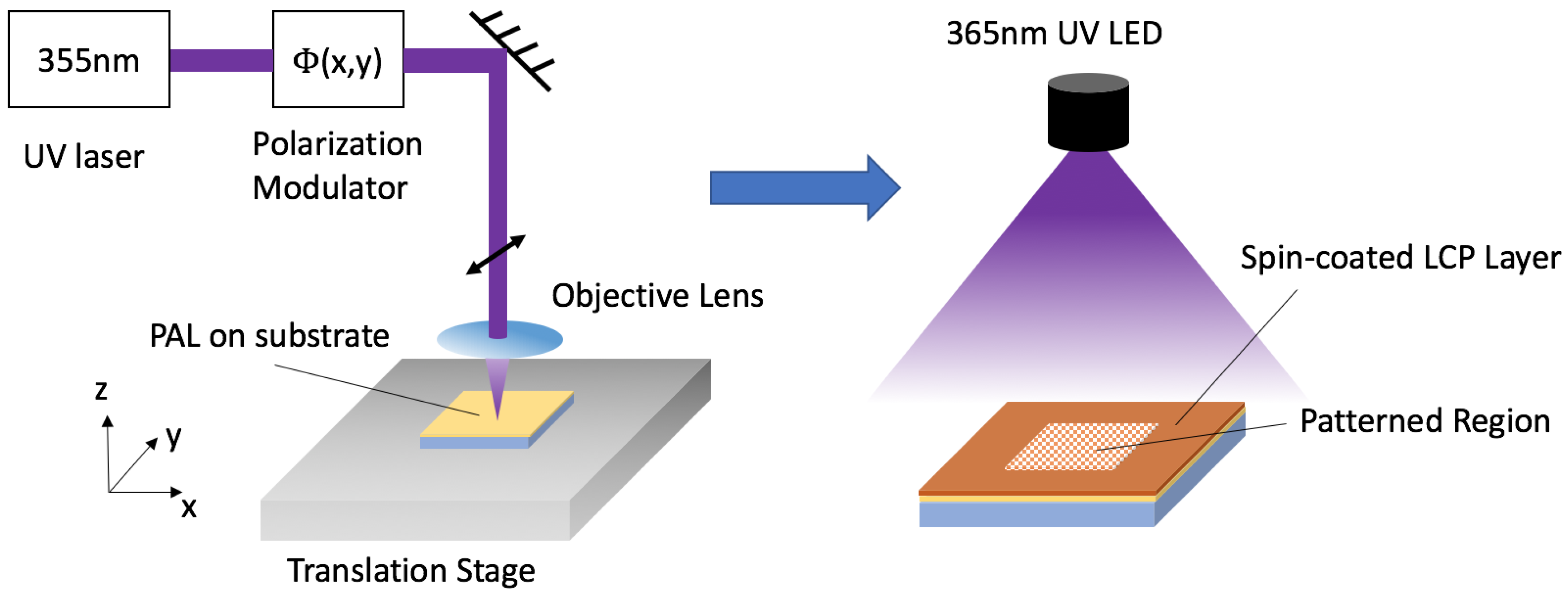
The GPHs in this work were fabricated as follows in
Figure 6. We begin with coating the azo-based PAL LIA-CO01 (DIC Corp) on clean glass (D263) substrates (spin: 30 s @ 1500 rpm, bake: 60 s @ 130 °C). For exposure, we employ the direct-write laser scanner with a solid-state 355-nm laser (Coherent Inc, Santa Clara, CA, USA). The substrate is secured on an XY translation stage by vacuum and raster scanned to record the phase pattern determined from the relation
at each pixel
. Exposure energy is set to 1 J/cm
2 to achieve adequate anchoring strength in the PAL. After exposure, the first LCP layer we coat serves the purpose of extending and enhancing the anchoring strength of the PAL to the second LCP layer. We use a first reactive mesogen solution, comprising solids RMM-A (Merck KGaA, Darmstadt, Germany,
@ 633 nm) in solvent propylene-glycol-methyl-ether-acetate (PGMEA from Sigma-Aldrich, St. Louis, MO, USA), with a 5% solids concentration. This is processed (spin: 60 s @ 1000 rpm, cure: 30 s @ 190 mW of UV illumination from a 365-nm LED in dry nitrogen environment) to create a thin LCP layer, which has little contribution to the retardation. For the subsequent two layers, we use a second reactive mesogen solution with higher birefringence, comprised of 20% RMM-B (Merck KGaA,
@ 633 nm) in solvent PGMEA. The processing is optimized to achieve maximum diffraction efficiency at 633 nm (spin: 60 s @ 1200 rpm, cure: 60 s @ 190 mW with a 365 nm LED in dry nitrogen environment).


