1. Introduction
Common rechargeable Li-ion batteries are based on liquid electrolytes, which places several restrictions on their design and dimensions. In addition, liquid electrolytes carry inherent safety risks, as was recently evidenced from high-profile incidents. All-solid-state batteries circumvent these limitations, facilitate design flexibility, and mitigate safety risks. The road to all-solid-state batteries was initially made through thin-film solid-state Li-ion batteries [
1,
2,
3], and has since evolved into the development of high-capacity three-dimensional battery architectures that increase the amount of electrode material within a given footprint [
4,
5,
6].
Besides being of technological interest, thin films of different battery components, especially active cathode materials, can be utilized for fundamental studies of the processes that govern the battery’s properties. Cathodes utilized in commercial lithium batteries are complex systems consisting of a polycrystalline active material in the form of a powder mixed with conductive carbon and a binding material. A simple system with no additives is desirable for use in the investigation of interfacial reactions, especially for local microstructural studies by transmission electron microscopy (TEM). Such systems, when synthesized in the form of a thin film, especially as a single (or pseudo-single) crystal epitaxial film, can provide powerful insight into the processes occurring on a well-described two-dimensional interface, as well as the film interior.
The research on cathode materials for lithium-ion batteries has been focused on different Li-intercalating oxides, as well as on olivine LiFePO
4 and their derivatives. Pulsed laser deposition (PLD) is a well-established method that is suitable for producing high-quality dense oxide films without post-deposition annealing. Several research groups have utilized PLD to deposit and study different epitaxial cathode films, such as layered LiCoO
2 [
7,
8,
9,
10,
11,
12,
13,
14], different Li-Mn-O structures [
15,
16,
17,
18,
19], and compositionally complex Li-TM-O (TM = Co, Mn, Ni) [
20,
21,
22,
23,
24]. In our previous work, we demonstrated that robust electrochemical measurements (cyclic voltammetry and impedance spectroscopy) can be performed on such binder-free films by utilizing SrRuO
3 (SRO)—Epitaxially deposited on single-crystal SrTiO
3 (STO) substrates—As a conductive electrode [
12]; with this approach, it has been shown that different stages of cycling can be studied by atomic resolution scanning TEM (STEM) [
13].
In this paper, we review the crystallographic basis that facilitates growing of epitaxial films of cathode oxide materials relevant for advanced Li-ion battery research. This basis becomes evident as we examine results from our previously (or yet to be published) reports on cathode materials that cover a range of chemistries and phases [
12,
13,
14,
15]. The underlying feature, namely the oxygen sublattice, is identified as the commonality between these different crystallographic phases, and the one that facilitates the observed epitaxial growth. With this understanding, one can predict the epitaxial relationships between different film phases and growth surfaces, and anticipate the presence of certain crystallographic features (i.e., variants). Experimental TEM results supporting the conclusions of the analysis are presented.
2. Crystallographic Information on the Structure of Oxide Cathode Materials
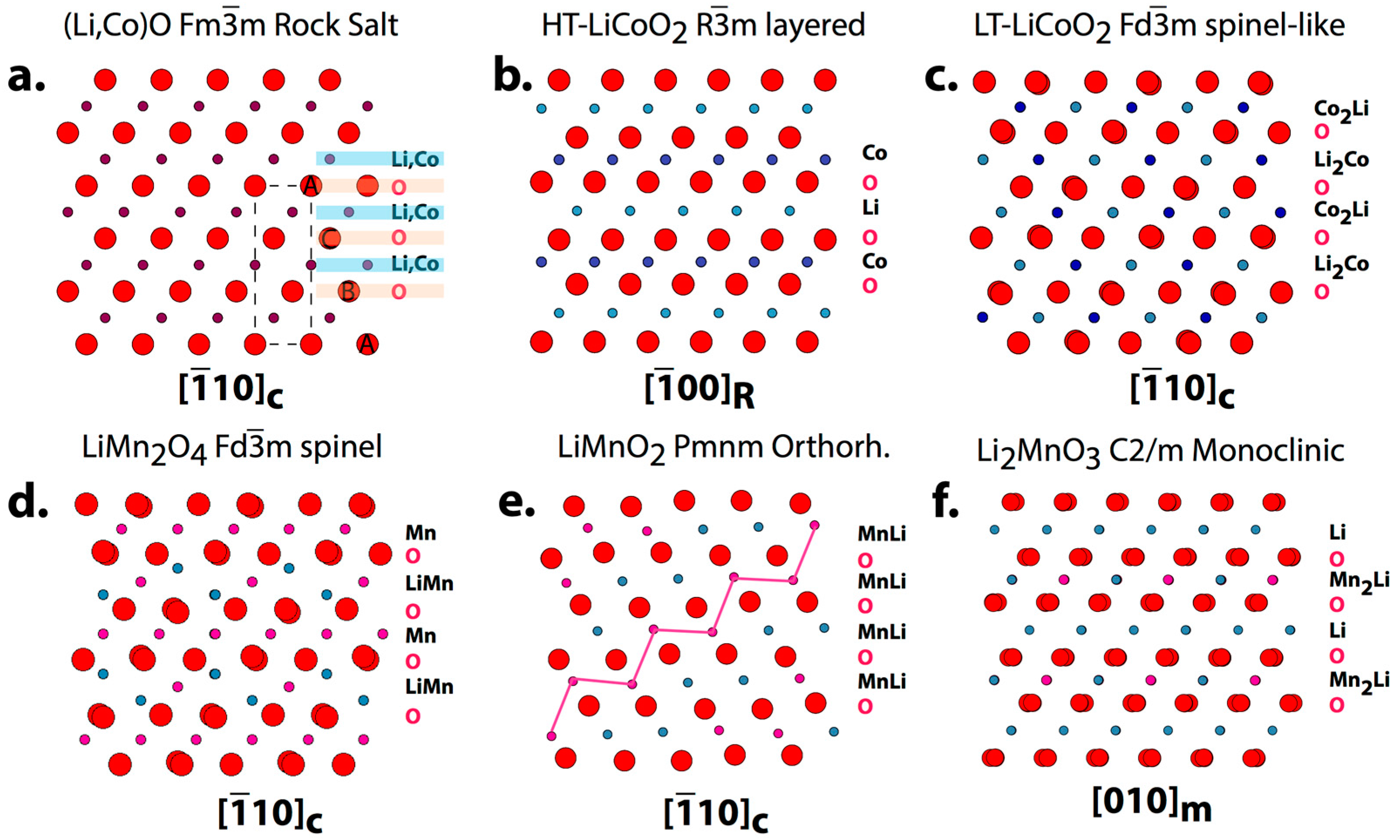
Table 1 lists the crystallographic information of different oxides that are either in use or under development as high capacity cathode materials. Despite having different space groups and lattice parameters, there is a common trait for these structures: A face-center cubic (FCC)-like oxygen sublattice, on which different ordering schemes of transition metals and Li ions establish different structures. The rock-salt structure was reported for CoO [
25,
26] and (Li, Co)O [
27] compounds, with 4a sites for O and 4b site for Co [or mixed (Co, Li)]. The rock-salt
Fmm cubic structure is shown in
Figure 1a as projected in the [
10]
c (c-cubic) direction; the projection depicts A-B-C-A-stacking of hexagonal oxygen layers, the (111)
c planes, with metal ions octahedrally coordinated between the oxygen layers. When mixed equivalent (Li, Co) sites are separated into all-Li and all-Co ions layers of selected (111)
c plane, as shown in
Figure 1b, the cubic symmetry is reduced to a trigonal
Rm of the α-NaFeO
2-structural type,
Table 1, of LiCoO
2 stoichiometry [
28]. In
Figure 1b, the trigonal structure is shown projected in the [
00]
R (R-rhombohedral) direction, and one of the (111)
c planes becomes (001)
R. For the LiCoO
2 structure, Li
1+ and Co
3+ remain in the octahedral sites, however, the size of the octahedra, and accordingly, the separation between oxygen layers, is different. Similar trigonal layered structures can be formed for compositionally more complex phases Li(Mn,Co,Ni)O
2, in which Co is partially or fully substituted by Mn and Ni (and some other elements) to improve performance, capacity, toxicity and cost [
29,
30,
31,
32,
33,
34,
35,
36], e.g., Li(Co
1/3Ni
1/3Mn
1/3)O
2 is well studied and commercialized.
The trigonal high temperature (HT)-LiCoO
2 structure forms at temperatures above 500 °C, while low temperature (LT) synthesis of the same stoichiometry results in the formation of the cubic structure denoted as LT-LiCoO
2 in
Table 1 [
37,
38,
39]. The structure of LT-LiCoO
2 was derived from the spinel-related phase
Fdm Li
2Ti
2O
4; for this structure, the oxygen network is similar to that of HT-LiCoO
2, however the distribution of Li and Co is different. For LT-LiCoO
2, the alternating layers are composed of Li
2Co and Co
2Li, with a hexagonal arrangement of ordered Li/Co, as shown in
Figure 1c. With such an arrangement, both Li and Co ions are octahedrally coordinated with oxygen, which is different from a true spinel AB
2O
4 structure, where the A atoms are tetrahedrally coordinated.
The true spinel structure is realized in LiMn
2O
4 [
40,
41,
42,
43,
44,
45], with Li occupying tetrahedral sites, as shown in
Figure 1d. This phase was studied as a possible substitution for LiCoO
2, for two main reasons: (a) three-dimensional diffusion of Li in the cubic structure is facilitated, enabling an anticipated high-rate performance, and (b) potential replacement of Co by the less expensive and environment-friendly Mn. Although LiMn
2O
4 was commercialized by several companies, it is known to suffer from low capacity (<120 mAh/g), and Mn solubility issues that affect cycle life. Manganese oxide LiMnO
2, with its higher capacity (theoretical 280 mAh/g), seems to be an attractive substitute cathode material for LiCoO
2 [
46,
47,
48]. The structure of the LiMnO
2 phase was initially identified as orthorhombic by Dittrich and Hoppe [
49], and was later refined by X-ray and neutron diffraction [
50,
51]. In our work, we used the
Pmnm space group with
a = 0.4574 nm,
b = 0.575 nm,
c = 0.281 nm lattice parameters [
51]. While in the cited works there is no consistency for labeling lattice axes, nor for identifying which lattice origin of the
Pmnm space group is used; from our high-resolution imaging results it was clear that Origin Choice 2 is correct [
15]. Although it is of the same stoichiometry as LiCoO
2, the LiMnO
2 structure has a very different arrangement, with zig-zag sequences of Li and Mn cations that alternate, and has the same orientation of the oxygen sublattice as other structures (
Figure 1e).
Another structure that is currently of great interest for high-capacity cathodes is Li
2MnO
3. Thackeray and co-workers first reported that mixed-phase Li-rich compounds are capable of nearly doubling the capacity of most existing intercalation cathodes’ chemistries [
52,
53]. The proposed formulation xLi
2MnO
3·(1-x)LiMO
2, with M = Ni, Mn, Co, and some other transition metals, was designed to have a mixture of monoclinic Li
2MnO
3 and trigonal LiMO
2 structures; the higher capacity of the composite is believed to be partially due to the presence of a monoclinic Li
2MnO
3 phase, which acts to stabilize the structure of the layered LiMO
2 phases during Li-extraction (charge). The Li
2MnO
3 structure was first determined as monoclinic in [
54], and later refined as having a
C2
/m space group (
Table 1) [
55], which we use in this work. In the layer notation, Li
2MnO
3 can be written as Li[Li
1/3Mn
2/3]O
2, where all-Li and Li
1/3Mn
2/3 layers of octahedra alternate. The structure is shown in
Figure 1f as projected in the [010]
m direction, which again shows ABCABC… stacking in the oxygen sublattice, which is similar to the structures discussed above.
3. Expected Orientation Relationship and Structural Variants for Oxide Cathode Materials Deposited on Perovskite Oxide Substrates
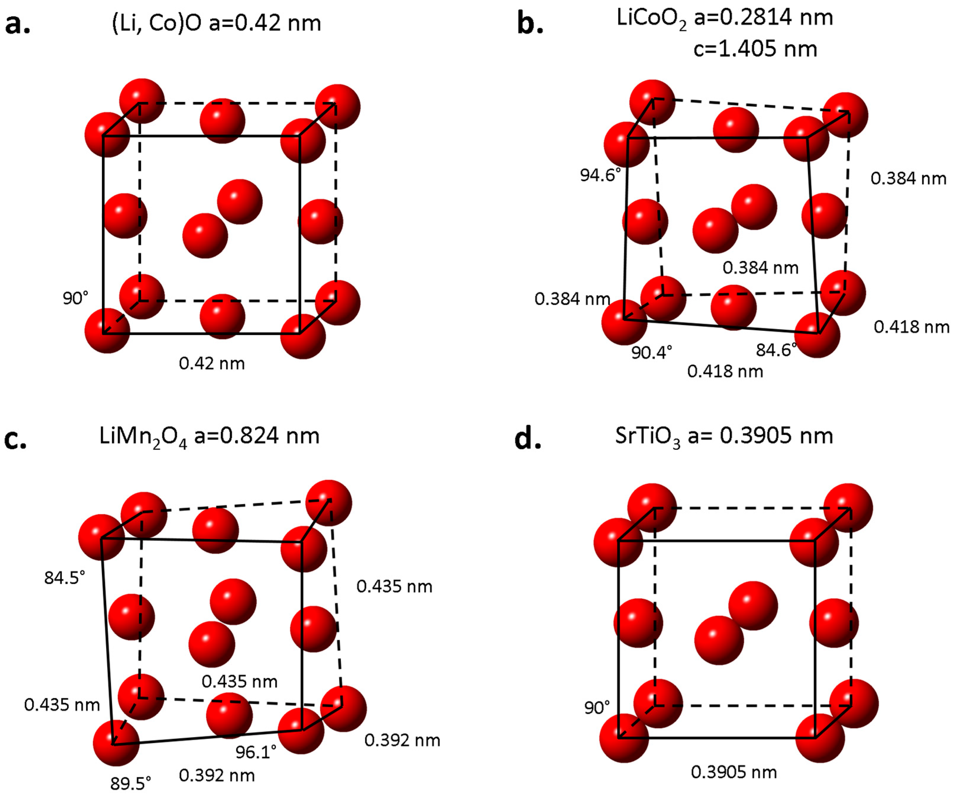
The structural information for a number of important cathode oxides shows underlying similarity: the structures can be considered to be different ordering schemes of Li and transition metal ions within the identified pseudo-cubic sublattice of oxygen anions that are arranged in a face-center cubic (FCC) fashion, as demonstrated for the rock-salt structure of (Li, Co)O shown in
Figure 2a. Whereas for (Li, Co)O, the oxygen sublattice is cubic, for other structures the FCC cell is distorted, with varying cell parameters and cell angles.
Figure 2 shows examples of the FCC-arranged oxygen cell for the trigonal LiCoO
2 (
Figure 2b) and the cubic LiMn
2O
4 (
Figure 2c). For LiCoO
2, the dimensions of the oxygen sublattice varies from 0.384 nm to 0.418 nm, and angles range from 84.6° to 94.6°; for LiMn
2O
4, the dimensions of the oxygen sublattice varies from 0.392 nm to 0.435 nm, and angles range from 84.5° to 96.1°. These pseudo-FCC cells of oxygen are comparable to the similarly structured oxygen sub-cell in perovskite SrTiO
3 and SrRuO
3.
Figure 2d shows the oxygen ions cell of STO with
a = 0.3905 nm (with Sr on the selected FCC sites, not shown). The analysis shows closeness of parameters and oxygen arrangement for the considered cathode oxides and STO/SRO, which suggests that the oxides can be grown on STO/SRO substrates epitaxially, with cube-on-cube orientations of their oxygen sublattices. This supposition appears to be realized experimentally for several compounds, in ours and other researchers’ works, and it will be presented in the following section.
Based on the suggested cube-on-cube relation, the following orientation relationships between cubic perovskite STO and cathode oxides are predicted:
Cubic (c) rock-salt (Li, Co)O, LiMn2O4 spinel and spinel-like LT-LiCoO2
(111)c//(111)STO and [001]c//[001]STO
Trigonal LiCoO2-type phases (R):
(001)R//(111)STO, (14)R//(001)STO (or [841]R//[100]STO)
Orthorhombic o-LiMnO2
(120)o//(111)STO and [001]o//[10]STO
Monoclinic m-Li2MnO3
(001)m//(111)STO and [010]m//[01]STO or (131)m//(001)c and [01]m//[100]c
These orientation relationships should result in a set of structural variants, although during film growth, realization of these variants is not of equal probability, due to differences between the planes that match with the substrate surfaces. For example, in trigonal LiCoO2, the set of four (111) planes of the pseudo-cubic oxygen cell are not equivalent, with only one (111) plane corresponding to (001)R, having six-fold symmetry, and being compatible with the (111) plane of an SRO/STO substrate. For the (001)R//(111)c, there are two rotational variants that differ by 180° rotation around [001]R, due to the three-fold symmetry of LiCoO2 (LCO). The other three (111) variants can contribute an additional six variants.
The orientation relationship between m-Li2MnO3 and cubic (c) STO (via pseudo-cubic SRO) was established as (001)m//(11)c and [010]m//[01]c; with such an orientation relationship, 12 variants are possible: three variants by 120° rotation around the directions normal to the four (111) planes of the pseudo-cubic oxygen sub-lattice.
4. Experimental Results from Transmission Electron Microscopy Studies
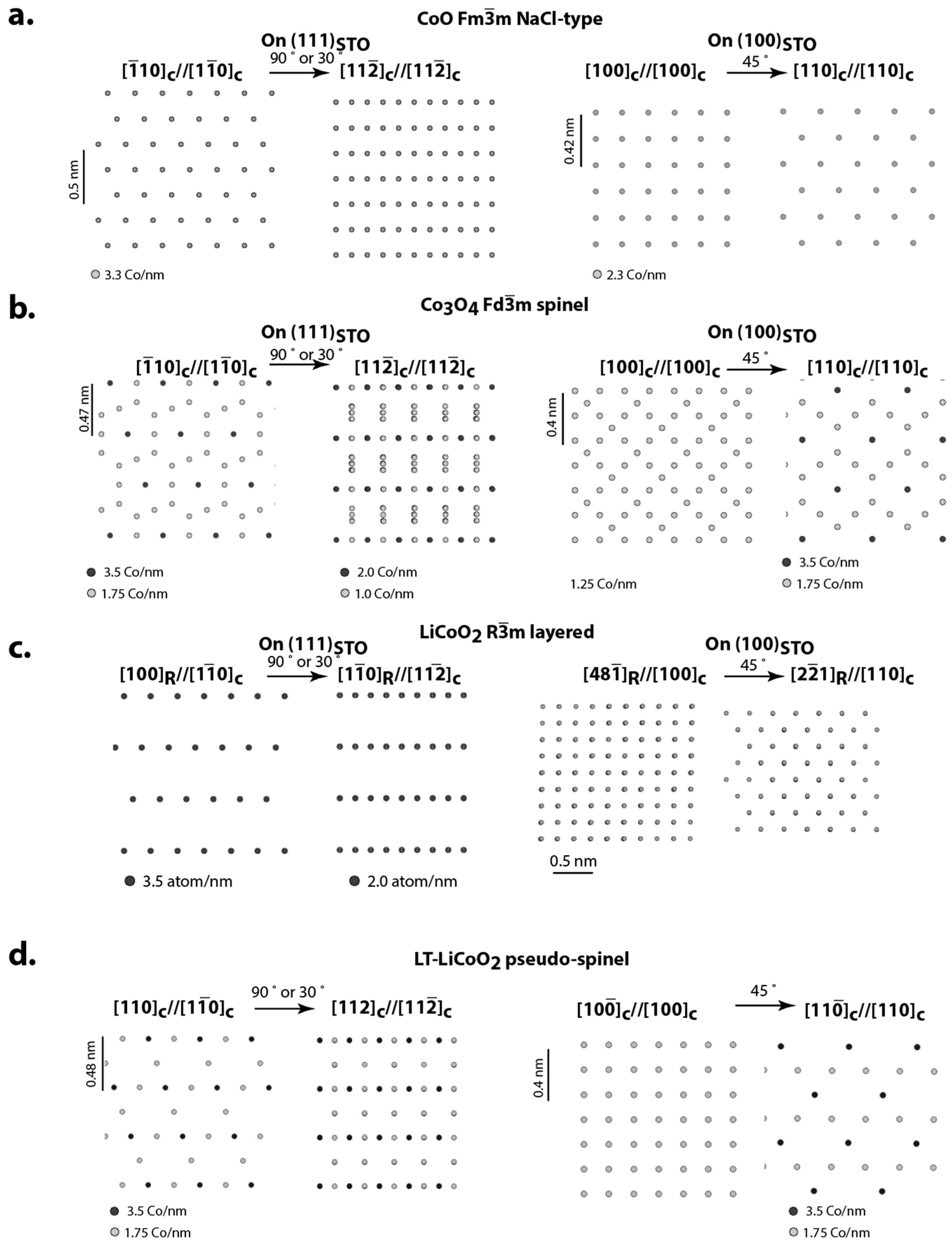
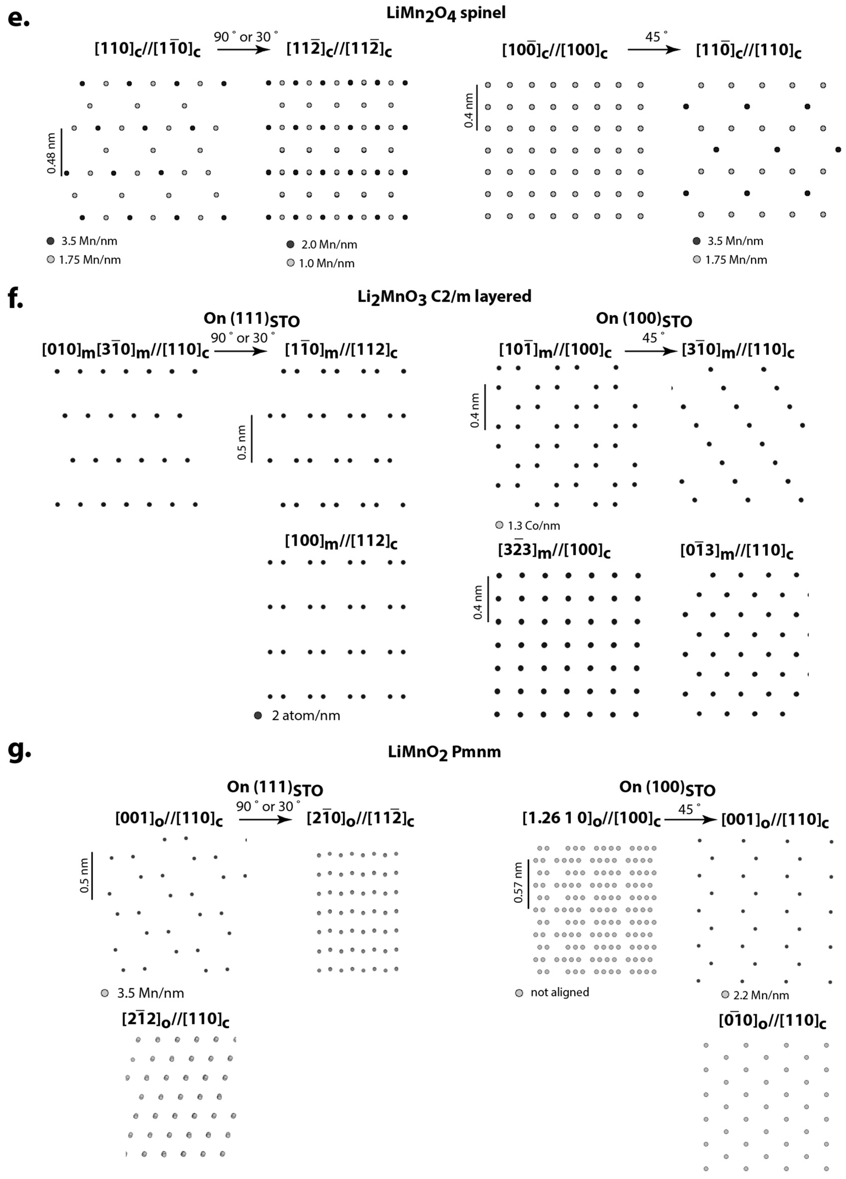
Below, we present experimental results on the epitaxial growth of different cathode film materials based on conventional TEM (including electron diffraction) and aberration-corrected STEM that uses a high-angle annular dark-field (HAADF) mode to image atomic columns of high-Z (atomic number) atoms [
56,
57]. The intensity of the columns is proportional to Z
α (where α is dependent on inner collection angle and detector geometry and approaches a limit of 2), whereas Z should be normalized to the linear density of atoms along a column. To see if the Z-contrast atomic imaging can distinguish between different structural arrangements, structural projections of high-Z transition metal atoms along the directions for the major structures of interest, relevant to experimental observation, were made (
Figure 3). In
Figure 3, the darkness of the circles corresponds to the atomic column density.
The films were deposited by using pulsed laser deposition (PLD) without post-deposition annealing [
58]. Considering the reactivity of Li in an oxygen environment, in order to compensate for losses of Li, the deposition targets had a concentration of Li that was higher than the intended composition of the film; e.g., to deposit LiCoO
2 films, the target of Li
1.4CoO
2 composition was utilized [
12,
13,
14]. Typical deposition conditions were as follows: 26 Pa oxygen pressure, 600 °C to 800 °C substrate temperature, 68 mm separation between target and substrate, and KrF excimer laser (248 nm) with 10 Hz repetitions and 0.8 J/cm
2 power. The films were deposited on STO single-crystal substrates with (111) and (100) surfaces, either bare or covered with conductive SRO for subsequent electrochemical testing. SRO layers, approximately 20–50 nm thick, were grown by PLD on STO before LCO, at a substrate temperature of 650 °C, using a SrRuO
3 target, and deposition conditions similar to the deposition of LCO [
12,
13].
4.1. LiCoO2 on STO and SRO/STO
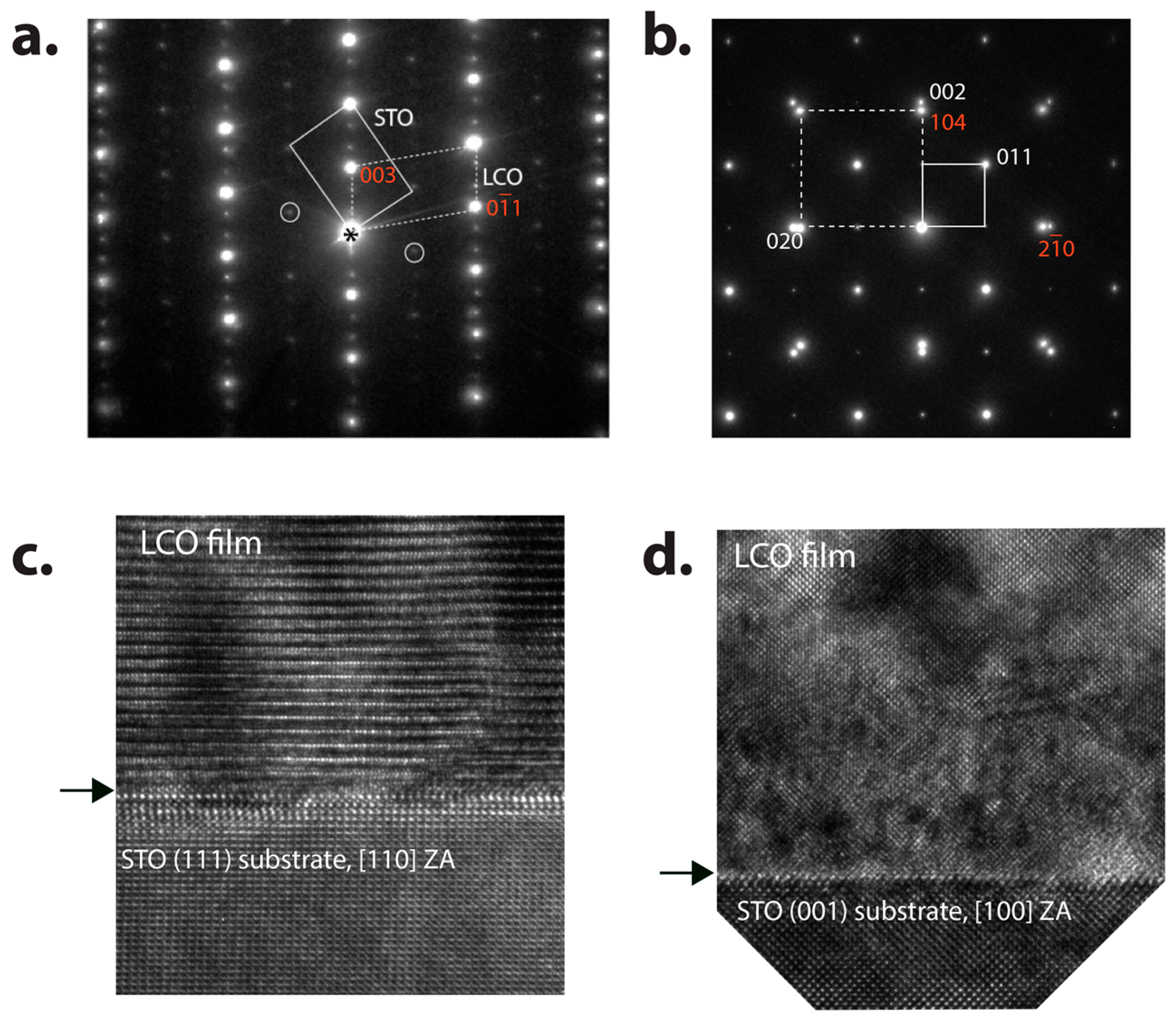
In
Figure 4, selected area electron diffraction (SAED) patterns from cross-sectioned samples of LCO films deposited on (a) (111) and (b) (100) surfaces of the STO substrate, are shown. The diffraction patterns include both film and substrate, and show the epitaxial, single-orientation of the films and their orientational relationships with the substrates. For (111)
STO, (
Figure 4a), the substrate is in a [1
0]
STO zone axis orientation, the film has HT-LiCoO
2 rhombohedral structure, and the orientation relationship with STO is established as (111)
STO//(001)
R-LCO, [1
0]
STO//[100]
R-LCO. Additional weaker reflections are from variants (twins) of R-LCO formed by 180°-rotation around the c-axis (plus double diffractions). In addition, rows of very weak reflections marked by circles suggest the presence of a small fraction of the cubic LT-LiCoO
2.
High-resolution images in
Figure 4c,d shows semi-coherent growth of the LCO film on the (111) and (100) STO interfaces, and structural imaging is comparable to the predicted structural projections in
Figure 3c, thus confirming the predominately HT-LiCoO
2 phase with [1
0]
R orientation in
Figure 4c, and the [48
]
R orientation in
Figure 4d.
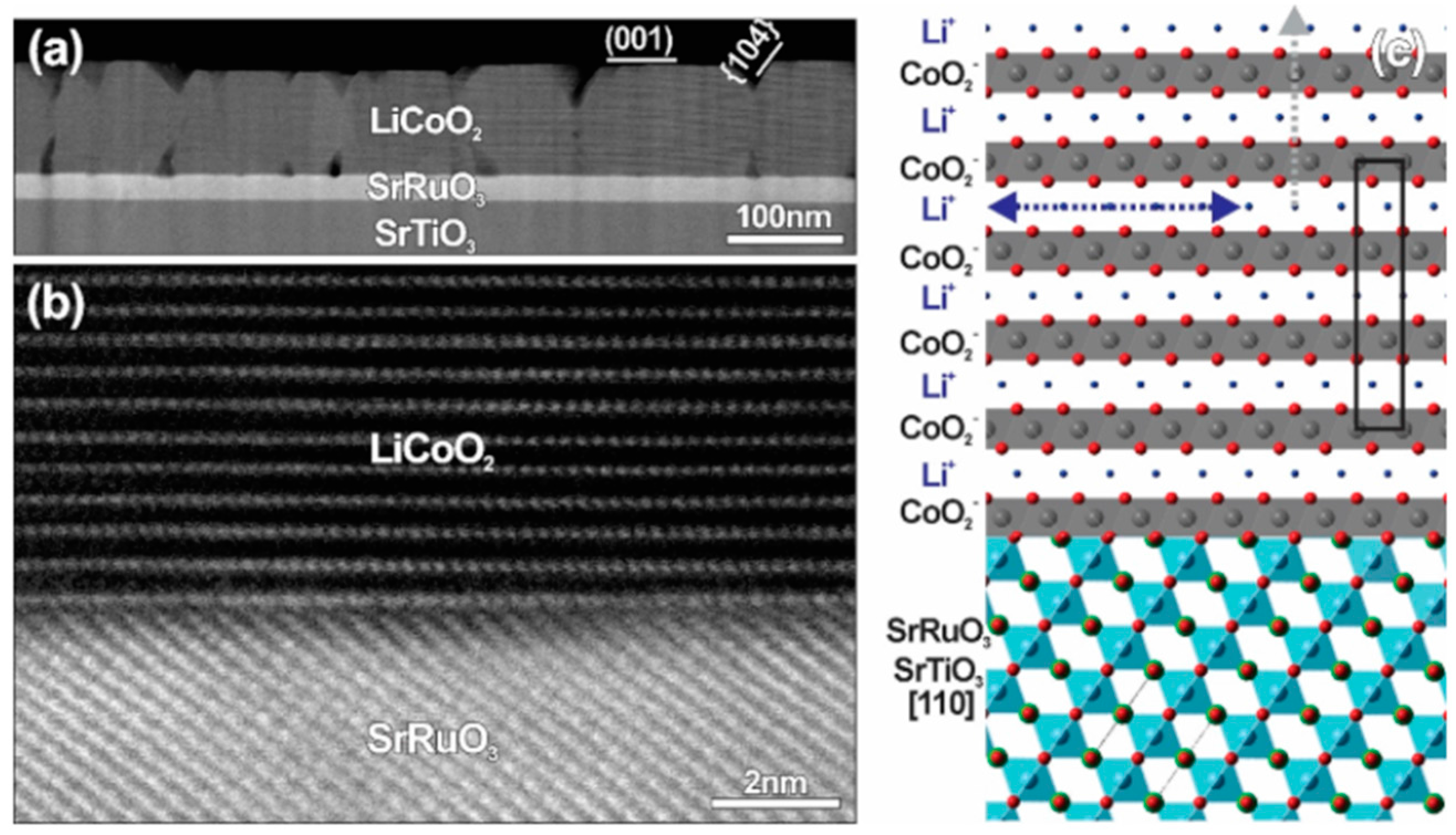
The same semi-coherent growth of LCO remains, for the deposition on STO, covered with conductive SRO, for electrochemical measurements of binder-free cathodes [
12,
13].
Figure 5a shows a HAADF-STEM image taken from the 111-film, with STO in a [110]
STO zone axis, and LCO in [110]
R. The STEM image shows an atomically sharp interface, where stacking of high-Z atoms, Sr and Ru for SRO, and Co for LCO, on both sides of the interface is clearly seen. An enlarged portion of the STEM image is shown in
Figure 5b. By overlap** the image with structural projections of the corresponding SRO and LCO structures (overlap** the bright spots of high-Z atoms with Sr/Ru and Co, respectively), the structural model for the interface can be analyzed, as shown in
Figure 5c. The model shows that ABC-stacking of oxygen ions in both SRO and LCO (outlined in the Figure) is interrupted across the interface, and has an ABCA||ABC sequence. Both the oxygen sequence and STEM contrast suggest that an immediate atomic layer on SRO has a mixture of Ru and Co transition metals from SRO and LCO respectively.
4.2. Li2MnO3 and LiMnO2 on SRO/STO
In our recent work, we explored the possibility of growing epitaxial m-Li
2MnO
3 by PLD, which is a phase of great interest for develo** high capacity intercalation cathodes for Li-ion batteries [
15]. The work showed that with a target of composition Li
2MnO
3, the desired monoclinic phase is deposited only at lower temperatures (close to 600 °C), whereas at higher temperatures, the orthorhombic LiMnO
2 phase forms. Formation of the lower-Li content o-LiMnO
2 phase at the temperatures above 700 °C was understood as having resulted from the loss of Li by oxidation, due to evaporation of lithium from the film at higher substrate temperatures, perhaps by the formation of lithium oxide (at 27 Pa oxygen pressure in a deposition chamber), or due to an increase in susceptibility of the film to sputtering by the plasma plume. The epitaxial growth of both Li-Mn-O phases on SRO/STO substrates of different orientations was demonstrated.
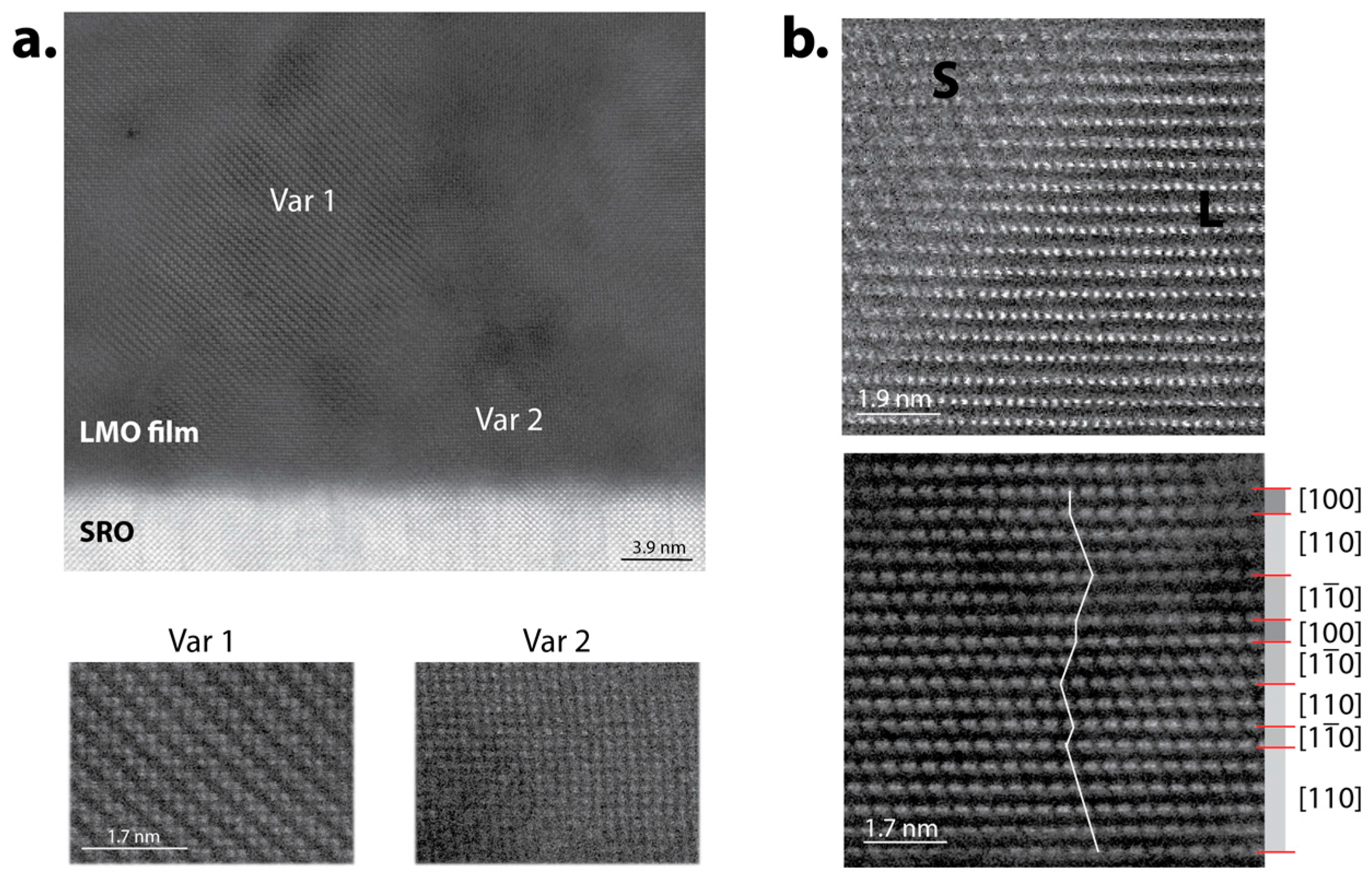
Figure 6 shows cross-sectioned HAADF-STEM images of Li-Mn-O films grown at 600 °C on SRO/STO(100) and SRO/STO(111) substrates. The crystal structure of the films was identified by analyzing the structural images, corresponding electron diffractions, and fast Fourier transforms (FFT) as monoclinic m-Li
2MnO
3. In
Figure 6a, a cross-section with STO in [100]
c zone axis shows a semi-coherent interface between SRO and the film; two coexisting variants can be identified by a pattern of Mn atom columns (see enlarged images below the overview image). Variant 1 shows a zig-zag pattern that fits m-Li
2MnO
3 in a [10
]
m zone axis, and Variant 2 is m-Li
2MnO
3 in a [3
3]
m zone axis, when compared to the simulated images in
Figure 3f. The variants are coherent to each other, which is expected for growth with a mutual pseudo-cubic oxygen sublattice. In
Figure 6b, two cross-sections for SRO/STO(111) are shown, one with STO in [1
0]
c (upper image), and another rotated 30° degrees, with STO in [11
]
c (lower image). For the upper image, the pattern is ambiguous and fits either the layered LiCoO
2-type, or Li
2MnO
3 in the [310]
m or [010]
m zone axis; however the lower cross-section for the [11
]
c zone axis clearly shows that the film has Li
2MnO
3 structure (compare with
Figure 3f). A zig-zag white line in the image emphasizes the changes in the stacking of Mn layers, which can also be considered as stacks of parallel slabs of variants with zone axes [1
0]
m, [
10]
m, [100]
m (the slabs are marked on the right side of the image).
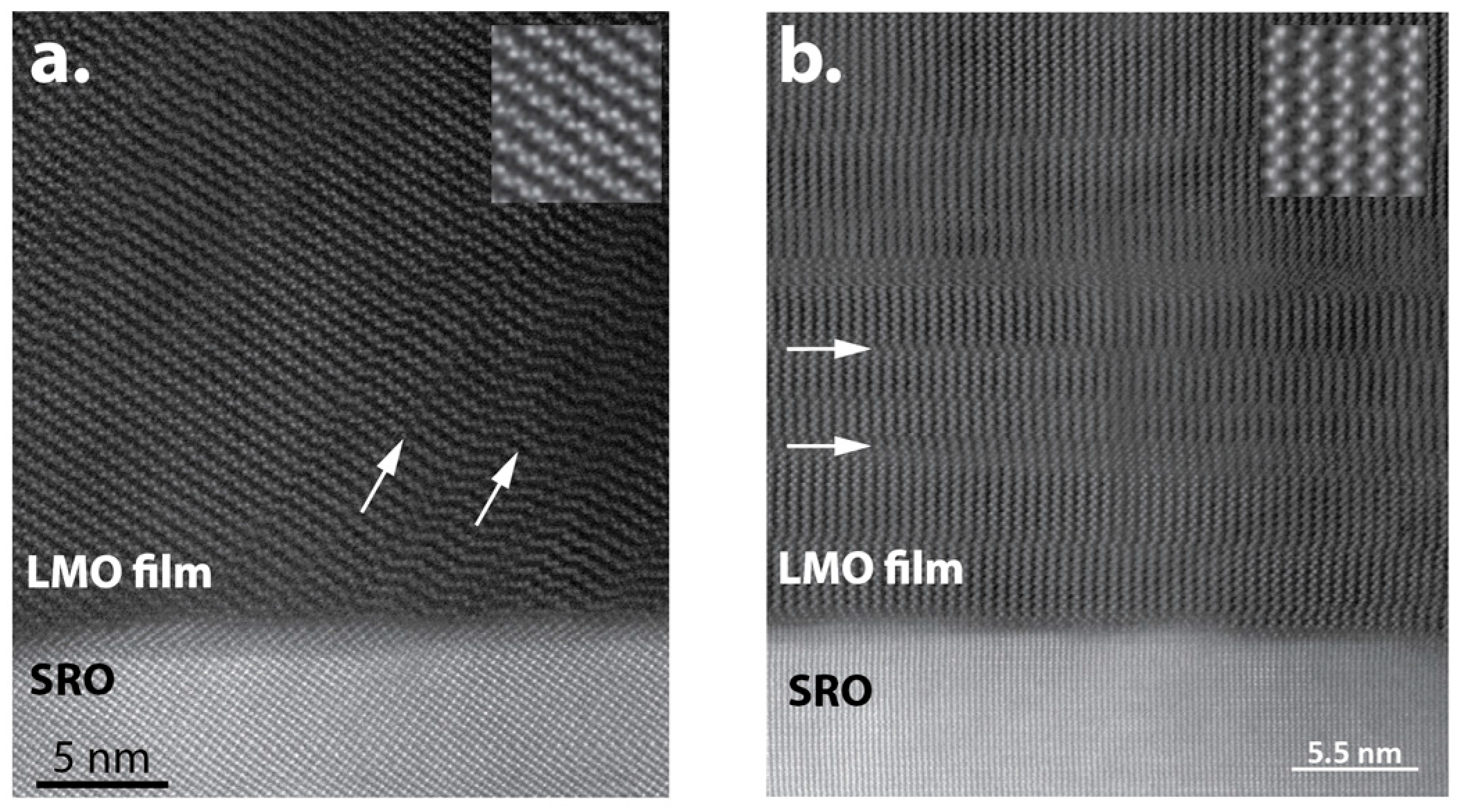
Figure 7 shows cross-sectional HAADF-STEM images of Li-Mn-O films grown at 800 °C on (a) SRO/STO(111) and (b) SRO/STO(100) substrates, where for both substrates, semi-coherent growth of the films on SRO is clear. The film was identified as having the o-LiMnO
2 structure, when the images were compared with projections of Mn columns in
Figure 3g. In
Figure 7a, the cross-section contains STO with a [110]
c zone axis along the beam direction, and the HAADF-STEM image has a zig-zag pattern that corresponds to o-LiMnO
2 in the [001]
o zone axis. In
Figure 7b, the cross-section has STO in the [110]
c orientation, and the HAADF-STEM image is of o-LiMnO
2, also in the [001]
o zone axis, but rotated 58.3° to match the (100) oxygen sublattice planes. Arrows in both images identify the presence of planar stacking faults parallel to a (100)
o plane.
4.3. Li1.2Mn0.55Ni0.15Co0.1O2 on SRO/STO
Growth of epitaxial compositionally complex films was demonstrated by using PLD with a target of Li
1.2Mn
0.55Ni
0.15Co
0.1O
2 (HE5050, Toda America Inc., Battle Creek, MI, USA). Although the composition was originally designed to have a mixture of two layered phases, m-Li
2MnO
3 and R-Li(Mn,Ni,Co)O
2, our results indicated the predominant formation of a single monoclinic Li
2(Mn,Ni,Co)O
3 phase. The formation of a single monoclinic phase agrees with studies by us and other authors identifying a powder of the same composition [
59,
60,
61].
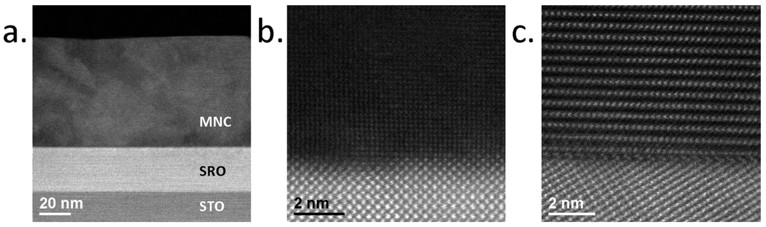
Figure 8 shows HAADF-STEM images of the Li
1.2Mn
0.55Ni
0.15Co
0.1O
2 (MNC) films grown at 600 °C on SRO/STO(100) and SRO/STO(111) substrate. According to the HAADF-STEM images, the film is predominately monoclinic Li
2(Mn,Ni,Co)O
3. The MNC/SRO interface at the STO(100)/STO[001]
c zone axis orientation (
Figure 8b) and at the STO(111)/ STO[110]
c zone axis orientation (
Figure 8c) demonstrates a well-defined film/SRO interface, and near-coherent growth of the film. This structure is very similar to that observed for the films of Li
2MnO
3, with alternating orientational variants (compare with the lower image in
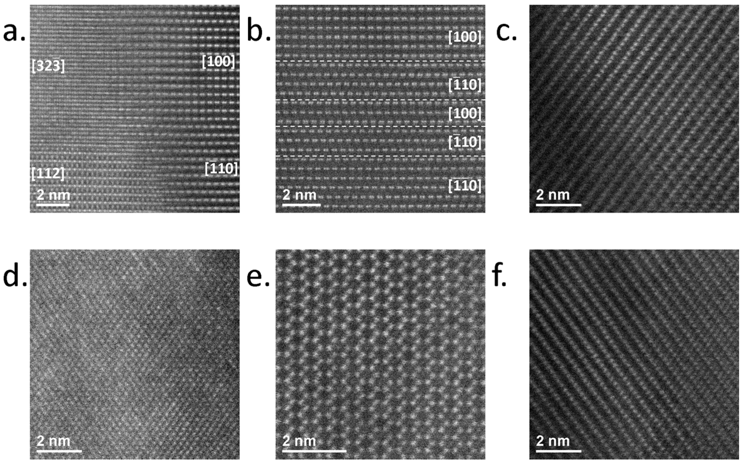
Figure 6b). Images in
Figure 9 show different variants as observed on STO(111) (a,b) and STO(100) (c–f)-grown films. Spinel (Li(Mn,Ni,Co)
2O
4, space group
Fdm) impurities, as indicated in
Figure 9a with a [112]
c orientation, were occasionally observed to be embedded coherently in the Li
2(Mn,Ni,Co)O
3 phase. Spinel phase surface reconstructions were also observed on select facets in powder samples [
59,
60,
61].
5. Conclusions
Epitaxial films of Li-ion battery systems give new insight into the electrochemical processes occurring in bulk, and at interfaces. In this paper, crystallographic analysis shows that many pertinent cathode oxides have an underlying similarity: the structures can be interpreted as different ordering schemes of Li and transition metal ions within a pseudo-cubic sublattice of oxygen anions arranged in a FCC fashion. Dimensions of this oxygen sublattice are compatible with several perovskite oxides that can be used as substrates for growing epitaxial films; with that proposition, the orientation relationships and structural variants for lower symmetry phases can be predicted.
Predicted epitaxial growth and crystallographic relations were experimentally verified for different oxide films deposited by PLD on single-crystal STO substrates of different orientations (some covered with epitaxial SRO for electrochemical testing), these are of interest for advanced Li-ion battery research. We provided results based on cross-sectional high-resolution TEM of the following materials: (a) the well-studied and commercialized layered trigonal LiCoO2; (b) orthorhombic LiMnO2, which has been considered as a LiCoO2 replacement in order to reduce costs; (c) monoclinic Li2MnO3, which provides a higher capacity, and has been studied for use either by itself, or in combination with layered Li(Mn,Ni,Co)O2 phases; (d) compositionally complex monoclinic Li1.2Mn0.55Ni0.15Co0.1O2, which was designed to have an integrated microstructure of Li2MnO3 and Li(Mn,Ni,Co)O2. All results demonstrated that epitaxial growth of these materials by PLD is possible, with high-resolution imaging showing near-coherent growth of the films. The growth follows the predicted cube-on-cube orientation relationship between the cubic and pseudo-cubic oxygen sublattices of a substrate and a film, respectively. The lower-than-cubic symmetry of the deposited oxides results in the formation of orientational variants (of the single epitaxial orientation relationship), although realization of the variants is controlled by the best compatibility with a substrate. While it is possible to predominately deposit a single phase, in many films, a small fraction of impurity phases is present, with the main impurity predominately being a spinel structure coherent with the surrounding matrix.


