1. Introduction
Gras** is one of the most widespread robot-associated tasks, both in industrial and nonindustrial environments. From a general perspective, robotic gras** depends on the means by which robots touch the physical objects around them. Such means are commonly defined as end-effectors, and do commonly feature two or more fingers.
Robotic gras** has great utility whenever repetitive and sometimes dangerous duties are involved. Examples of applications can be found in several fields, such as food and agriculture [
1,
2,
3], marine robotics [
4], etc. To successfully achieve object gras**, specific end-effectors, namely grippers, might be employed.
Nowadays, a wide variety of robotic grippers are available on the market; they differ in terms of size, fingers, maximum stroke, maximum grip** force, actuation technology, etc. A comprehensive overview on the trends for industrial grippers is provided by [
5]. The majority of these devices work as simple, fully open or fully closed mechanisms. Their actuation is often pneumatic, achieving, on one hand, smaller size and power consumption with respect to, e.g., the electric ones, but complicating, on the other hand, the control of the fingers’ position and of the gras** force. Despite its widespread diffusion, robotic gras** is still characterized by rather basic performance, and does not yet match the outstanding progress of robotics. This particularly applies to the industrial environment, where grippers have commonly no more than two fingers and execute simple pick-and-place tasks [
6].
In contrast with the past few decades, the last 10 years saw considerable progress in the development of robotic grippers. This trend can be inferred from the published articles and cumulative citations shown in
Figure 1.
In all of these works, the used control approach was addressed, though it did not always represent the principal theme. Before 2013, few articles mentioned closed-loop controllers for robotic grippers; the absence of references before the new century is almost total. Accurate and effective control architectures, in terms of, e.g., grip** force and finger positioning, might lead to enhanced performance of robotic grippers, allowing for more advanced manipulation. Scientific research on this topic, i.e., the control of robotic grippers, is variegated, due to the wide range of control applications and technologies that can be used to design these mechanisms. As a matter of fact, the majority of control algorithms available in literature remain in the laboratories, finding scarce application in real industry and complicating the enhancement of the robotic grippers’ performance.
Objectives
In light of the above considerations, the present article aims at providing a thorough overview of the control strategies for robotic grippers. To the best of the authors’ knowledge, no other review specifically addressed such a topic. Previous reviews did concentrate on robotic grippers for specific domains of application. For instance, authors in [
1] focused on agricultural robots, which are called upon to perform delicate gras** actions, especially when interacting with fruits and vegetables. Moreover, in [
2,
3] were reviewed soft grippers for crop harvesting and handling, suggesting a major interest towards automation in the food industry. In [
4] were considered only grippers operating underwater, while other reviews tackled aspects like finger design criteria [
7] or statistics concerning the industrial market [
5].
With respect to the sole piezoelectrically actuated microgrippers, ref. [
8] recently highlighted their main control strategies.
Instead, the present article provides a systematic collection of the main contributions to the control of robotic grippers. Namely, force and position controls were gathered, with no focus on other variables such as slip and of relevant compensation techniques (on this subject, see [
9]), which go beyond the scope of the review. The cited works will be grouped and briefly discussed with respect to the employed control approach. A discussion on the main control approaches and on their usage will be presented as well, to help the reader achieve a complete view of the field. Articles from the same authors, presenting similar strategies, will be discarded, and only the most relevant (e.g., journal publications) will be mentioned. Note also that schemes and graphs from cited works will not be reported; it is preferred to let the reader consult each of such works in order to retrieve content of interest.
The remainder of this article is organized as follows:
Section 2 summarizes the actuation principles and sensors used on robotic grippers,
Section 3 covers the main control strategies and relevant works,
Section 4 contains considerations and comprehensive statistics and finally
Section 5 highlights the conclusions. Please note that only articles that provide experimental results are included in this review, discarding reports in which only theory and simulations are illustrated.
3. Control Strategies
This section will address the main strategies used to control robotic grippers. A brief overview of the working principles will be provided, highlighting advantages and drawbacks for the specific application. It is worth noticing that some of the cited works propose a control approach where more techniques are involved. Therefore, hybrid control structures will be grouped based on which one may be considered the core of the gripper control, according to the authors’ opinion and regardless of the gripper type or actuation.
3.1. Proportional Integrative Derivative
The well-known proportional, integrative, derivative controller (PID) is widely used in modern industry due to its effectiveness and ease of implementation [
15,
16]. In its simplest form, it consists of a feedback control architecture based on three separate actions associated with as many parameters, i.e., gains: proportional
, integral
and derivative
. These gains multiply, respectively, the error
between the setpoint and the measured value, the integral and derivative function of such an error. The summation of the so-obtained contributions becomes the controller output
. In the time domain, the PID can be described as
The proportional action accounts for the current value of
e(t); the integral action accounts for the accumulated
e(t) over time; the derivative action accounts for the rate of change of the error
e(t). Configurations where only one or two of these actions exist are possible (i.e., P, PI or PD). Several methods for tuning
,
and
are available [
17]. However, in the case of robotic grippers, manual and semiempirical trial-and-error tuning might be effective. In fact, multiple experimental trials are rapidly executable on these devices with low risk of damage. Although a certain debate still exists about the PID tuning and related methods [
18], such a control technique remains among the most preferred ones.
In [
19], an early implementation of a PI force controller for a rigid, two-fingered pneumatic gripper might be found. The gripper was equipped with a simple force sensor placed on the fingertip. A PID-based master–slave finger architecture was shown in [
20]. Here, each finger was equipped with its own DC motor and could be force- or position-controlled. In particular, the master finger was controlled in position through a PID. Instead, the slave finger used a PI for force control fed by a force sensor, whose output was employed in the master finger PID.
The idea to adopt tactile sensors was conceived towards the creation of efficient force controllers, and therefore of enhanced gras** capabilities. In this direction, a three-fingered gripper employed in [
21] had all the fingertips equipped with tactile force sensors. A cascade-loop PI configuration was used: the first PI acted directly on the force compensation while the second one was used for the inner current control loop of the DC motor. In [
22], a custom-made force sensor composed of a resistive element incorporated into a deformable membrane allowed for the closure of the PI force loop of a pneumatic gripper. The servo-actuated gripper in [
23] made use of a force sensor placed on one finger to provide feedback for a PID controller, and more recently, a PID was integrated in a closed-loop force control relying on tactile sensors, which were mounted on each of the two gripper fingers and capable of measuring the grip force [
24].
Differently, in [
25], a PID position control with angular feedback for an hydraulic gripper was employed. The angle sensors were placed at the base of the fingers. Two PID architectures were used for an underactuated gripper in [
26], one for controlling the DC motors producing the fingers actuation; the remaining one for actuating some belts mounted on the fingers to augment the gras** capabilities. Moreover, commercial electric grippers, such as the one adopted in [
27], are generally controlled with standard PIDs as regards both the fingers position and the motor current.
Other applications [
28,
29] showed how to set up separate PIDs dedicated to the actuation control of multiple fingers. In [
28], DC motors provided with encoders were used to drive each of the three fingers of a commercial gripper, which were in turn equipped with as many tactile force sensors. Each finger was position-controlled with a PID, whereas a simple proportional force control component was added for each of them. Instead, in [
29], six DC motors, i.e., two per finger, were controlled by means of a single PID to manage the position of the fingers.
PIDs were also used for soft gripper control. Recent applications are seen in [
30,
31,
32]. In [
30] a PID position control for pneumatic soft actuators was developed. A three-fingered soft gripper was constructed using as many soft actuators, resulting in a device capable of delicate gras**. A flex sensor provided the angular displacement of the finger and the chambers of the soft actuators were driven by three-way solenoid valves. Another PID was used for the bending angle control of the fingers of a soft gripper in [
31]. In this case, the bending sensors were calibrated by means of a laser sensor, which provided the bending distance, while the bending angle was calculated analytically based on such a distance. In [
32] was presented a PID pressure/force control of a pneumatically actuated soft gripper featuring pneumatic touch sensing chambers, which could grasp objects of different shapes and rigidity with constant PID gains.
Furthermore, a peculiar, uncommon implementation was presented in [
33], where images from a camera are used as bending deformation feedback for a PID controller. In this manner, it was possible to manage the bending angle of a soft finger mounted on an SMA-based planar gripper.
Microgripper control benefits from the PID scheme as well. Constant fingertip displacements were achieved with a model-free PID of an ionic polymer metal composite-actuated microgripper [
34]. PIDs were used for piezoelectric microgrippers in [
35,
36], proving their ability to effectively compensate for hysteretic behaviors.
In [
37], an electric gripper mechanism for delta robots was proposed. The implemented controller included a set value generator that interpolated a position set point to generate smooth trajectory with trapezoidal ramp profiles, and a three-level cascade rotation controller, i.e., P-P-PI, for current, velocity and position, respectively. Further, an additional current controller including a PI and two feedforward channels (motor current and desired force), was set to adjust the gras** force.
To conclude this subsection, another interesting option regarding the PID implementation is so-called gain scheduling. Different sets of
,
and
might be defined in accordance with the gripper operational regions. In fact, a unique ensemble of gains may be insufficient for the controller to achieve a decent error under all the operative conditions. For instance, a gain scheduler was programmed in [
34] to perform position control of a microgripper consisting of two fingers made of ionic polymer metal composite. Another example of gain scheduling, applied on a magnetic series elastic actuator for robotic grippers, might be viewed in [
38]. In this case, the objective was to better tune the microgripper torque control.
Finally, it is worth observing that PIDs are frequently employed as part of more complex control strategies, as will be evidenced in the following subsections.
3.2. Optimization Based Control
Optimization-based controllers offer the possibility to define and manage a set of constraints, resulting in minimized (or maximized) control output without exploiting heuristics procedures. Nonetheless, literature concerning robotic grippers provides few examples of such controllers; most of them are centered on the quadratic programming (QP) formulation. A similar formulation implies the minimization of a quadratic function, which is subject to linear constraints. Mathematically, assuming a variable
x to be minimized, the QP problem has the general form below:
In (
2),
Q is the positive, semidefinite Hessian matrix and
q is the gradient vector. The equation
contains the linear equality constraint while
are the linear inequality constraint.
and
are the lower- and upper-bound constraint vectors. Apart from achieving a minimized control output, the QP permits to develop a control action that takes into account the saturation limits of the actuators. For instance, in the case of a pneumatic gripper, the bound constraints might coincide with the maximum and minimum output voltage of the pressure regulator, whereas the variable
x might be a vector containing the desired pressures in the gripper chambers. For a more in-depth dissertation on the solution of QP problems, please refer to [
39].
A force controller for a pneumatic gripper, based on a QP function, was developed in [
40]. A similar approach, again based on a QP function, was used in [
41], where a more sophisticated control algorithm was proposed, including an extended Kalman filter and a second-order model of the external pressure regulators that drive the pneumatic gripper. Another QP-based algorithm was used in [
42], employing a two-level nested controller with as many PIDs and gain schedulers for closed-loop control of the grip** force and air pressure of a pneumatic gripper, while also compensating for internal friction effects. The control objective in all three above mentioned articles was to calculate the two desired optimized, i.e., minimized, pressures to be sent to the gripper chambers. To close the loop on the gras** force, in the first two works a force sensor was mounted between the gripper fingers, whereas in the third work, a load cell was integrated in one of the gripper fingers. Moreover, a QP-based control architecture involving more detailed friction analysis was employed in [
43] to accurately control the position of the gripper fingers. The QP implementation resorted in this case to pressure and position measurements.
Finally, when the optimization problem is solved involving a certain number of future time instants, the model predictive control (MPC) formulation is achieved. For instance, in [
44], such a formulation was combined with vision feedback to ameliorate the manipulation performed by a robotic gripper. This approach proved to be robust, yet the presence of a camera at 18.5 cm from the manipulated object surface complicated the setup.
3.3. Fuzzy
A fuzzy controller is a nonlinear, static, multi-input–multi-output controller. Such a controller may be built upon the experience of a human operator. It provides a formal methodology for representing the human heuristic knowledge of a specific process or system.
The fuzzy controller consists of four elements, as represented in the scheme of
Figure 2:
A rule-based set of if–then rules, which contains the expert’s knowledge on how to control the system.
An inference mechanism, which interprets and applies the rule-base knowledge to control the system. It has three stages: matching, selection of rules and conclusion.
A fuzzification interface, which converts controller crisp inputs, i.e., a precise value of a measurable quantity, to fuzzy sets that heuristically quantify the meaning of linguistic variables.
A defuzzification interface, which converts the conclusions of the inference mechanism into actual inputs for the process.
For further explanation on the fuzzy control strategy, please see [
45].
In the control of robotic grippers (but not only), fuzzy control is often used in combination with other control strategies. Consider, e.g., [
46], where the gains of the PID controller, managing the fingers’ position of a flexible gripper, were tuned through fuzzy logic. Further, in [
47] a similar logic was adopted to control the force produced by an SMA-wire-actuated gripper, using a load cell to measure the grip force.
Authors in [
48] employed an adaptive fuzzy PID position control with a modified Smith predictor to eliminate the hysteresis delay, improving the performance of a microgripper actuated by a piezoelectric cantilever. The control system obtained object position and end-effector position by means of image processing.
A combined approach was developed in [
49] where the control architecture for a robotic gripper included impedance, fuzzy logic and iterative learning. The impedance control allowed the robot interaction with the environment to be adjusted, employing both position and force information. The iterative learning process was used to optimize the rules of the fuzzy controller. The resulting fuzzy impedance controller was designed to estimate the best impedance parameters in real time when grip** unknown objects.
An adaptive inverse dead-zone control method is proposed in [
50]. Such a method leverages a Takagi–Sugeno fuzzy model to improve the performance of an heavy duty gripper driven by hydraulic motors. The Takagi–Sugeno fuzzy interface handles the defuzzification computations through a simpler algorithm, namely weighted average, when compared to standard fuzzy interface. The latter makes use of geometrical calculations instead. Consequently, the Takagi–Sugeno method is more computationally efficient, and high precision in the gripper angular displacement was achieved.
By means of fuzzy schemes, the controller might handle nonmodeled parameters. In [
51], fuzzy logic was implemented to allow a gripper to apply proper force in order to grasp unknown objects with different masses, dimensions, and coefficients of friction.
Agricultural robotics may also benefit from the introduction of fuzzy controllers. In [
52], a fuzzy control scheme for an electric gripper deputed to harvest strawberries was presented. The controller was used to regulate the desired equivalent force, calculated from the weighted average of the total force applied on each finger.
In [
53], fuzzy logic was implemented to control the variation of the actuator torque in order to adjust contact force of underactuated fingers using tactile and position sensors. Both the error between desired and sensed force and between desired and measured force derivative were used as input to the fuzzy controller.
Finally, recalling that fuzzy logic is often combined with other control modes, in [
54], a fuzzy sliding mode control was utilized to control a microgripper. The microgripper was driven by two independent microfiber-composite actuators; the right actuator was used to position the micro-object and the left one to control the force. The fuzzy sliding mode control, with a nonlinear adaptive law, was employed to control the microgripper fingers position. In fact, fuzzy logic was useful to adaptively vary the switching gain of the sliding mode controller, increasing its robustness towards system uncertainties. Moreover, a PI controller was used to control the force, estimated with a force observer. Two laser sensors were used to measure the output displacement of the fingers.
The next section presents the aforementioned sliding mode control in more detail, as well as additional studies based on joint use of such a control mode with fuzzy logic.
3.4. Sliding Mode Control
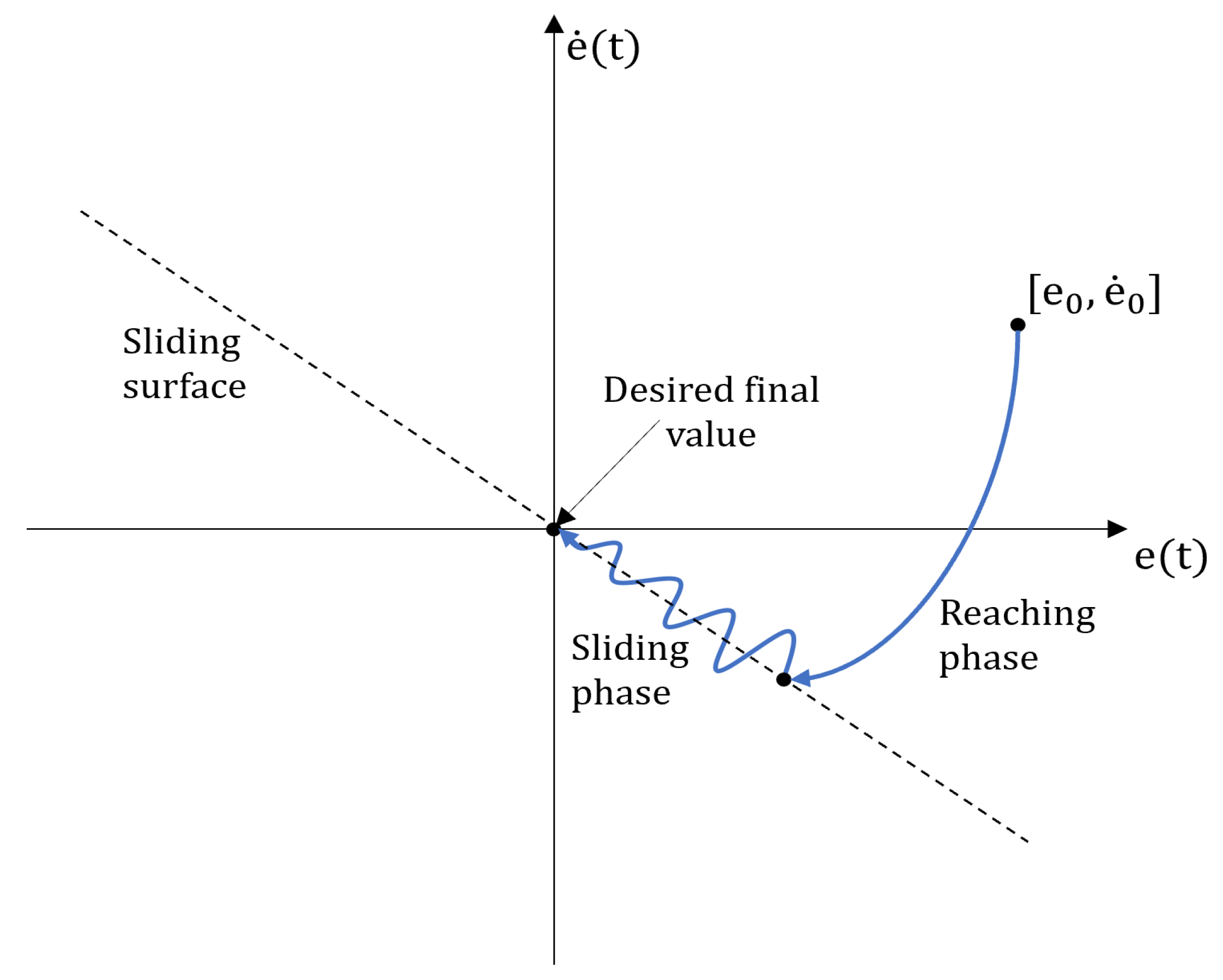
The sliding mode control (SMC) is a nonlinear control technique.The main idea underlying SMC is to force (reaching phase) and keep (sliding phase) the system state towards a chosen surface, i.e., the sliding surface. This is carried out by means of a discontinuous control action; therefore, SMC is defined as a variable structure control.
To briefly introduce the basics of SMC design, let us consider a standard control tracking problem: the output variable y must follow as closely as possible the desired setpoint . Hence, an error is to be defined. The development of a standard SMC passes through two main steps:
A generic sliding manifold
can be written as follows:
where
are positive parameters. In many applications, a common choice for Equation (
3) is:
in which only a single time derivative of the error is included. However, the derivative degree to include is
, where
r is the relative degree of the input–output dynamics: this is equal to the number of times the output should be derived to explicitly observe the input, when the system is in state-space representation. If
is correctly designed, the solutions of the resulting differential equation when
is expected to have
e tending to zero. This condition can be reached with a proper control signal
u that might be simply modeled as:
with
U being a positive constant that must be selected to keep
as close as possible to zero. Ideally,
u should be characterized by infinite frequency to avoid chattering problems in proximity of the sliding surface. In practice, this is not possible and represents the main downside of SMC, since chattering problems cause unwanted vibration and may induce hardware damage and low steady-state accuracy. A representation of the SMC is depicted in
Figure 3. More complex formulations, e.g., higher-order SMC, are useful to reduce chattering. An example of second-order SMC [
55] is the so-called super twisting SMC (STSMC) that introduces a control law continuous in time, unlike the discontinuous one, the first-order SMC defined by Equation (
5). The SMC theory and its more complex formulations can be retrieved from the relevant literature, such as [
56,
57].
SMC has found broad application in microgrippers: such grippers are usually driven by piezoelectric actuators, which are known for their microscale operations and compact sizes. These kinds of actuators are prone to hysteresis; hence, SMC-based strategies were successfully used to contrast this source of nonlinearity. For example, in [
58], a discrete SMC was implemented for closed-loop control of nanoscale displacements; the hysteretic behavior was handled without any chattering, and the displacements were read by ad hoc sensors embedded in the used amplifier. In [
59] was proposed a discrete SMC for impedance control based on a second-order dynamic system model, able to achieve both position and force control; the first was measured by a laser displacement sensor, whereas the latter was estimated by a force observer. Moreover, this controller did not resort to creep or hysteresis models. A position/force control for a compliant microgripper structure was shown in [
60]; it was proven how a discrete SMC for the gripper position could work efficiently alongside a PID-based force control, providing a smooth control switch. Furthermore, in [
61], the same author made use of a system model built only on input–output data for a digital SMC implementation to control a piezo-driven micropositioning system. Again, the hysteresis model was not envisaged. In [
62] was presented a constant-force microgripper: the constant force was achieved by means of an ad hoc designed compliant mechanism, while a discrete-time SMC was again implemented to control the gripper displacement.Position control of a microgripper was achieved in [
63] with an adaptive version of SMC, an online model parameter estimation and a Kalman-filtered position, sensed by a laser sensor. Finally, an adaptive version of backstep** SMC was employed in [
64] for position tracking of a compliant microgripper and chattering countering. In principle, the backstep** approach uses a recursive method to simplify a high-order system into a less complex and lower-order series of systems to be controlled. An inverse hysteresis model compensator for the piezoelectric actuator of the microgripper was also employed. Two laser sensors where used to capture the jaws’ displacement.
The greater performance of an STSMC over a first-order SMC in managing the chattering phenomenon was shown on force control of a gripper actuated by a servomotor [
65]. In this case, the right fingertip was equipped with a force sensor, while the left fingertip was equipped with a slip sensor. Interestingly, the authors found that the chattering for the first-order SMC increased when gras** stiffer objects: in this respect, STSMC had more reliable performance.
In [
66] was presented an example of the combined use of a fuzzy controller and an SMC (FSMC) for the force control of a DC-motor-driven gripper. This had the advantage of being a model-free approach, since the calculated sliding variable became the input for a fuzzy logic controller.Moreover, the FSMC was also used for the end-effector positioning.
In [
67] was shown an SMC force control for a flexible gripper; this was actuated by a piezoceramic actuator, and the state variables of the system were estimated through force sensor readings.
A control architecture based on a SMC with a fuzzy sliding surface and a disturbance observer was proposed in [
68]. By using this approach, the authors intended to propose a controller capable of working with a wide range of grippers. In fact, the integration of fuzzy logic in SMC served to enhance the controller performance with respect to grasp uncertainties. However, preliminary tests performed on a real setup showed behavior degradation due to unmodeled nonlinearities, introducing chattering.
Finally, a few examples of SMC used for SMA-actuated grippers might be found. In [
69], the fingertip position of an SMA-wire-actuated gripper was controlled using SMC. The controller relied on a second-order polynomial fit in order to relate the finger displacement with the change in the SMA electrical resistance. Hence, this implementation did not require any external sensor. Finally, in [
70], another fuzzy SMC was employed for the force control of an SMA-actuated gripper, equipped with a force sensor. Here, the sliding variable provided the input to the fuzzy logic which featured eleven Gaussian membership functions, allowing for defuzzification and featuring smooth and concise notation [
71].
3.5. Machine Learning Techniques
Machine learning (ML)-based architectures were extensively used for robotic gras** within the last years. ML applications can be regarded as a sort of optimization problems. The main difference with the optimization approaches used in control theory and, more specifically, discussed in
Section 3.2, is the fact that ML relies mostly on data. The vast majority of ML applications aim to determine object localization, pose estimation and grasp estimation for manipulation [
72], often employing vision-based algorithms [
73]. Although interesting, these studies fall outside the scope of the present review, since they do not strictly concern the control of the grippers themselves. Below is provided a generic ML scheme (
Figure 4) as well as a concise selection of articles where ML was at least involved in the estimation of parameters useful for the gripper controller.
Multiple ML algorithms were tested on a flexible compliant gripper, actuated by a stepper motor, to estimate and predict its optimal finger displacement [
74]. Here, some embedded sensors in the flexible structure of the gripper were used to distinguish the concave or convex shape of the items; such information was useful for defining the gras** action. For this application, an extreme learning machine (ELM) proved better prediction performance with respect to several ML methods such as the two support vector regressors (with different kernel functions), artificial neural networks (ANN), neurofuzzy, etc. In [
75], a simple control policy was built upon ML-based contact force estimation; the used algorithms were shallow NN (i.e., few hidden layers) and locally weighted projection regression. All of them outperformed the proposed analytical force estimation, with a three-layer NN being the best among the others. In [
76], a framework combining deep ANNs and logistic regressions was proposed to respectively learn the physical properties of the grasped object (e.g., mass, stiffness, surface roughness, etc.) and to predict the grip status. This information was then used to compute an optimal grip position command. The objective was to apply the minimal gras** force required in order to hold an item. Furthermore, it was shown how reinforcement learning (RL) could be used to compute the optimum grip** position of objects with variable size. The RL framework made use of simulations to speed up the learning process, whereas the real gripper was a two-finger electric one. Another RL structure was implemented in [
77] for a stepper-motor-driven gripper equipped with eight commercial force sensors. A stable grasp was first defined for a certain object and it was set as the objective state of the gras** adaptation procedure. Then, the online RL made use of a learning algorithm, namely Q-learning, to learn such an objective gras** condition. However, the proposed procedure took about 5 min to complete the learning process, given a certain object to grasp.
Finally, for the SMA-actuated gripper presented in [
78], ML models permitted one to successfully predict displacement and force through regression. Moreover, the stiffness of the grasped object was estimated through regression and classification. A backpropagation NN (BPNN) and long-short term memory (LSTM) were used. Specifically, BPNN refers to an NN using backpropagation for training. Instead, LSTM is generally used whenever temporal information needs to be memorized by the network. Such an ability of LSTM was useful to cope with the hysteretic behavior of the SMA, leading LSTM to better predict in terms of accuracy and robustness. For regression and classification purposes, voltage and resistance of the SMA were used as inputs to the models.
3.6. Other Control Architectures
The literature contains documents describing control architectures that are hardly classifiable among the previous categories. This descends from the very specific tasks upon which such architectures were developed.
For instance, impedance control was occasionally mentioned in the previous sections when discussing fuzzy or SMC control strategies. However, impedance control is broadly used in robotics and some implementations were attempted within the considered domain, i.e., robotic gripper control. The same applies for adaptive control. In this section, a number of these implementations will be listed.
An early impedance control example might be found in [
79] for an electric gripper driven by two DC servomotors, one for each finger. The position, velocity and acceleration feedbacks were used to handle mechanical compliance, dam** and inertial behavior, respectively. Both velocity and acceleration were obtained by differentiating the position. In particular, the acceleration feedback was utilized to reduce the impact forces of the fingers closing on an object.
In [
80,
81], peculiar applications were presented. The authors of [
80] proposed an adaptive version of the impedance control, which enhanced its ability to to better cope with stiffness uncertainties during apple gras**. This was performed by introducing a small position correction on the fingers, which, in turn, adjusted the gras** force measured through force sensors mounted on the fingers. Instead, in [
81], an underwater gras** task was presented. Such a task was performed by means of a gripper equipped with a force sensor and an encoder. It was shown how environmental uncertainties could be processed online through a recursive least-squares algorithm with a forgetting factor, and thus compensated through impedance control.
A particular design was proposed in [
82] for a pneumatic soft gripper. The soft structure of the fingers was precharged through a one-way valve, while the fingers’ velocity and bending angle were controlled by pulling or releasing nylon tendons, actuated by two servomotors. The use of tendons facilitates the control, since the fingers’ bending angle and velocity linearly related with the motor position and velocity. This soft prototype had a force sensor and a proximity sensor, installed on one of the two fingers. The proximity sensor was used to reach a preset safety region where the approaching speed of the finger was drastically reduced to avoid damaging the object, instead the force sensor was used to reach a predefined grip** force. After the desired force was reached, the closing speed was set to zero.
In [
83], an adaptive control structure made use of gripper force feedback statistics, sensed by two F/T sensors mounted on the fingers, to better adapt to varying contact interaction impedance. Specifically, the controller compensation made use of a real-time calculated probability of grip failure, given a certain critical force of failure, which was assumed constant. Moreover, it was also shown how Kalman filtering could be implemented to estimate the object impedance for enhanced adaptability of the controller. Another adaptive control structure for minimal gras** force was developed in [
84], based on object slip velocity and force feedback respectively sensed by a slip sensor and a force sensor. The former was placed on one finger, whereas the latter was placed on the remaining finger. A force-dependent friction disturbance rejection and backlash compensation was presented in [
85] for a DC-motor-driven gripper. Finally, in [
86], the position control of the three fingers of a pneumatic gripper is tackled by means of a fractional order PID (FOPID) coupled with a finite-time prescribed performance control (FT-PPC). The FOPID formulation, when compared to the classical PID, adds two more parameters acting on the integral and derivative component for enhanced versatility at the cost of a more challenging tuning procedure. The FOPID was integrated with a FT-PPC, whose main idea is to add output or error constraints and force them into a prescribed area. This is accomplished by means of a prescribed performance function, which acts on both the transient and period.
4. Discussion
Robotic grippers can be designed and built with diverse actuation principles, sensors, materials, fingers etc. (see
Section 2.1). Regardless the constructive features, critical control problems to be solved still regard the development of reliable links between actuation and output force, which has to be exerted on the grasped object. Indeed, fine control of gras** force is not straightforward due to several factors, including frictional effects and nonlinearity sources, such as the air flow inside the chambers of pneumatic grippers.
Instead, the control of the fingers’ position reached an acceptable level for industrial applications, especially for what concerns electric grippers. Pneumatic ones still suffer from low controllability, both in terms of force and position, and often behave in fully open and fully closed fashion [
43].
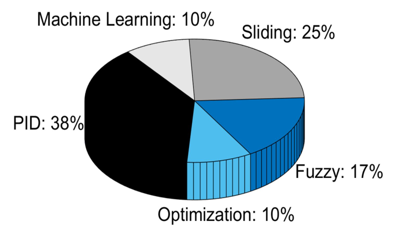
Notwithstanding the remarkable, constant enhancement of robotic technologies, the advancement of grippers is experiencing a slower growth. Considering the sole references cited in this review, which, to the best of the authors’ knowledge, offer a complete overview of the field, some interesting statistics can be extracted. The pie chart in
Figure 5 is divided according to the control modes percentage.
As is evident, traditional control methods such as PID and SMC represent the most common choices when carrying out research in laboratories. This also derives from the large employment occurred in the past decades, especially for what concerns the PID. It is interesting to note that, while PIDs are used mostly to control rigid grippers, SMC is instead preferred for the control of microgrippers. This is probably related with the fact that piezoelectric actuation, mostly employed in microgripper design, normally works at high frequencies up to about 600 kHz [
87]. This is an ideal condition for SMC applications, where operational frequency is critical for implementation. Furthermore, it must be noted that fuzzy controllers did not find implementation in the soft grippers, at least as far as concerns the cited articles. This may derive from the nature of fuzzy logic, which does not seem to fit the functioning of soft grippers due to its incapability to capture nonlinear behaviors and other uncertainties typical of such grippers. Based on purely heuristic rules, mainly defined through human observation, this type of control logic is probably not yet deemed mature enough to deal with actuators embedded in soft grippers. All these aspects are detailed in the three charts of
Figure 6.
In general, the PID architecture found application in many gras** scenarios due to its easy implementation, and was successfully implemented as a standalone controller or else in combination with other control modes. Modern engineering software allows for automatic procedures of gain tuning on the basis of selected bandwidth, phase margin and plant transfer function (when available). Even if PID does not always guarantee optimal control and often requires a certain system linearity to perform well, it is often the first choice for grippers’ closed-loop control regardless of the type of actuation. Moreover, some of its limitations may be overcome through techniques such as gain scheduling, which allows for the definition of a map of gains for different working regions and, if required, for different input signals. Nonetheless, this complicates the gain tuning, and frequently, PID gains are not robust to even small changes in the experimental setup, necessitating further transfer functions designed ad hoc to reject disturbances.
SMC-based strategies may be applied to robotic grippers, especially when there is the need to compensate for hysteretic effects (e.g., in piezoelectrically actuated grippers). However, chattering problems are difficult to solve completely even with more complex formulations of SMC, such as STSMC, or even predictive SMC (SMPC), which combines SMC and MPC [
88]. As a consequence, SMC may represent a good choice whenever a certain amount of chattering can be tolerated. Further, the definition of the sliding surface, in particular the number of error derivatives to include in its formulation, might be challenging. Moreover, the coefficients are not straightforward to select, even though their choice is often arbitrary.
Fuzzy logic, which began to significantly spread in the last decade, is also investigated by researchers in the control of robotic grippers. Fuzzy control privileges the use of heuristic information over complex mathematics, allowing one to build nonlinear controllers in the absence of detailed models. Nonetheless, as the heuristic information comes from human operators, who have to carefully observe the system behavior, the consequent definition of the fuzzy rules might not adequately take into account unforeseen events as well as disturbances. Due to the paramount role of heuristics carried by fuzzy logic, its usage in industrial grippers is still scarce. It is worth noticing that, as already evidenced in
Section 3.3, fuzzy logic often acts as a tool to enhance other control architectures, such as PIDs. Nevertheless, in the authors’ opinion, no clear advantage seems to emerge from the incorporation of fuzzy logic to enhance the robustness of PIDs in the control of robotic grippers. For instance, when using PIDs, a well-designed gain scheduling is to be preferred. In general, conducting a comprehensive study of uncertainties affecting the gripper behavior represents a more reliable approach to the gripper control. By contrast, fuzzy logic introduces an often unnecessary level of complexity stemming from the subjective nature of its human-based heuristic rules.
On the other hand, optimization-based controllers started being employed in the last 5 years on robotic grippers. Optimization requires a model of the gripper physics, particularly of the jaw–finger subsystem. The controller performance depends on the accuracy and on the detail contained in such a model; yet, it may be difficult to formulate, especially in the case of soft or compliant mechanisms. Moreover, the execution time of the selected optimization solver must be kept in consideration. Generally, QP permits fast computation cycles (<1 ms), though it may not be sufficient when high (>1 kHz) sampling frequency is required. As a general trend, MPC and QP are preferred on moving robotic systems rather than on grippers, when sophisticated trajectories need to be planned and followed.
The use of ML for control of robotic grippers appears less common than the abovementioned classical approaches, such as PID and SMC. This may descend from the poor instrumentation of industrial grip** devices, which implies reduced quantities (or even complete absence) of data available to build reliable ML frameworks. Despite the progress in the construction of ML architectures, which has led to simpler implementation and faster training, it remains complicated to deliver to industrial customers similar solutions for the control of robotic grippers. Algorithms involving the use of cameras are already on duty in industrial environments, though they serve more to identify objects and contours rather than to control the gripper itself.
Table 1 provides an overview of the advantages and disadvantages of each controller type for robotic grippers. Despite the promises, none of the presented controllers, except the PID ones, are currently employed in real applications. Regrettably, the range of control methods in industrial grippers is drastically limited. For instance, as described earlier in this review, experimental works proved the optimization algorithms ability to confer force and position control on pneumatic grippers, which usually do not resort on such controls. Nonetheless, before a real acceptance might occur in the industrial robotics community, a large time span is easy to envisage. The same applies to SMC algorithms, even though high potentiality when applied to microgrippers was shown.
Notwithstanding the effort spent in the conception and implementation of control approaches, robotic grippers remain still far from being able to perform complex manipulation tasks that would allow them to operate in fully unstructured environments. The role of robotic grippers, deemed as “pivotal” in the advancement of modern automation processes [
5], seems not to receive satisfactory attention by researchers. As a matter of fact, soft robotics have concentrated much of the effort in the last years, leading to a certain progress in the development of soft grippers that are almost never suitable for heavy industrial tasks, and rather suit fragile objects [
32]. Hence, industrial scenarios feature robotic gras** tasks that are frequently tailored to items with specific, a priori known characteristics; such items are often prepositioned in the robot working area so that the gripper is eventually required to perform minimal or no intelligent action in order to accomplish the gras** task. Even when provided with force or position feedback, the gras** ability of robotic grippers, in particular industrial ones, rarely involves properties such as weight, shape and roughness of the object to be grasped. A crucial part of the gripper, i.e., the finger, seldom comes to be instrumented with sensors that could enhance the performance of the gripper itself. One may think about the cost and technological effort required by the miniaturization and integration of F/T sensors in gripper fingers: another aspect that, notwithstanding the considerable impact it would produce, draws poor attention [
89].
A significant step forward, in this direction, may be the integration of tactile sensing technologies in grippers fingers. Indeed, despite the promising forecasts of 2–3 decades ago, such sensors are totally unemployed outside research laboratories. Tactile sensing may also provide knowledge on the type of touched material, its shape, roughness, temperature, etc., allowing one to create advanced control algorithms that account for all this information. They may also represent a richer yet cost-effective alternative to the expensive, hard-to-integrate force/torque sensors occasionally embedded in the fingers of robotic grippers.


