1. Introduction
Due to the influence and limitations of geographical location and surrounding environment, problems such as poor geological conditions, shallow burial depth, tight engineering land, complex surrounding environment, and strict control standards are common [
1,
2]. To overcome these challenges, double-arch tunnels are widely used in urban tunnels because of their advantages of convenient portal selection, smooth route, land conservation, beautiful section shape, and relatively small impact on the surrounding environment [
3,
4]. However, urban double-arch tunnels also have limitations, such as long construction period, high cost, various procedures, complex supporting structure, more intersection of excavation and supporting construction surfaces, and difficult quality control [
5,
6,
7]. Additionally, with the construction of special underground projects involving environmental protection and surface cultural relics, an increasing number of ultra-shallow tunnels have been constructed. Hence, during the excavation and support process of an urban ultra-shallow buried double-arch tunnel with complex geological conditions, the stability of tunnel surrounding rock and the deformation control of surrounding underground pipelines have become issues that need special attention [
8,
9]. According to modern tunnel theory, the surrounding rock is the main body to bear the unloading stress caused by excavation. In the process of tunnel construction, effective technical means are necessary to adopt to maximize the self-supporting capacity of the surrounding rock. Such means improve the stability of the surrounding rock and tunnel structure, which can not only improve the safety of a project during construction, but also improves the quality and service life of the tunnel structure during operation [
10,
11]. To strengthen the bearing capacity of the rock mass and avoid possible risks in construction, various methods and measures are often adopted in the project, such as advance support, small pipe reinforcement, and grouting reinforcement to reinforce the surrounding rock [
12,
13,
14,
15,
16,
17]. Compared with other treatment methods, grouting reinforcement technology has the advantages of high efficiency, convenience, low cost, wide treatment range, and good reinforcement effect, especially in rock and soil with high fragmentation degree [
18,
19,
20]. The principle of grouting reinforcement technology is to use cement slurry, water glass, cement mortar, chemical grout, and other materials to fill the voids of broken rock masses effectively to improve the compactness, integrity, tension, compression, shear, and creep of the rock mass, so as to maintain the stability of rock mass [
21]. The strength and stability of grouted surrounding rock formed after grouting reinforcement of broken rock mass is not only an important index to evaluate the effect of grouting reinforcement, but also a key parameter to determine the deformation and the self-supporting capacity of the surrounding rock.
Extensive research has been carried out on grouting and reinforcement of surrounding rocks and remarkable results have been achieved. Zong et al. [
22,
23] found that the stiffness, roughness, peak shear strength, residual strength, and shear strength parameters of structural surface after grouting reinforcement were significantly improved. Niu et al. [
14] studied the grouting diffusion law, splitting grouting reinforcement mechanisms and grouting reinforcement effects using 3D simulated grouting test system. The uniaxial compressive strength of filled soil after grouting increased by 186%, the permeability coefficient decreased by 47 times, and the cohesion and internal friction angle increased by 45.3% and 44.9%, respectively. Evdokimov et al. [
24] compared and analyzed the shear strength parameters of fractured rock before and after grouting consolidation, and considered that grouting significantly increased the shear strength of fractured rock. Moosavi et al. [
25] found that when the water–cement ratio was 0.4 and 0.5, respectively, the peak and residual shear strength of grouted surrounding rock increased with the increasing normal stress. Taking the grouting reinforcement project of a large section cavern surrounding rock as the background, Cheng et al. [
26] found a linear relationship between grouting volume and grouting pressure, hydraulic conductivity, and grouting time, and a square root relationship between slurry diffusion radius and grouting pressure, hydraulic conductivity, and grouting time through numerical simulations. On the basis of the tunnel crossing railway stations, Lu et al. [
27] used ANSYS software to simulate and analyze the grouting reinforcement effect of tunnel surrounding rock according to the equivalent continuous medium theory. The results show that grouting reinforcement has a good effect on reducing surface settlement and horizontal convergence. Through grouting experiments on fully weathered granite, Yang et al. [
28] studied the diffusion law of cement rule of different viscosity and the influence of grout viscosity on the reinforcement effect, and found that an increase of slurry viscosity strengthens compressive strength and shear strength. Liu et al. [
29] found that the tensile strength of rock cracks increases with increasing grouting viscosity, but the overall tensile strength was low. Ma et al. [
30] found that broken fine sandstone reinforced by compaction grouting slurry has obvious ductility, strong plasticity, and deformation resistance, and can remain stable in a large deformation range. Li et al. [
31] took the compressive strength, deformation modulus and hydraulic conductivity of grouting reinforced rock mass as the evaluation index of grouting reinforcement effect, tested the grouting plus solid effect under different water–cement ratio and curing time, and found that slurry water–cement ratio has a significant impact on grouting reinforcement effect. Wang et al. [
32] found that grouting reinforcement can effectively suppress the stress concentration at the crack tip, improve the integrity of the specimen, avoid the formation of stress redistribution, and enhance the integrity of the specimen.
Generally, the research on grouting reinforcement of surrounding rock has mostly studied the strength comparison and deformation analysis before and after grouting. However, only few studies have been conducted on the strength of grouted surrounding rock and how to determine grouting parameters of rock mass in engineering. With the land part of Haicang undersea tunnel as a background, laboratory experiments, literature analysis, and numerical simulation were performed to study the method and rationality of determining the grouting parameters of the surrounding rock of the ultra-shallow buried double-arch tunnel. The results can be referred by similar projects.
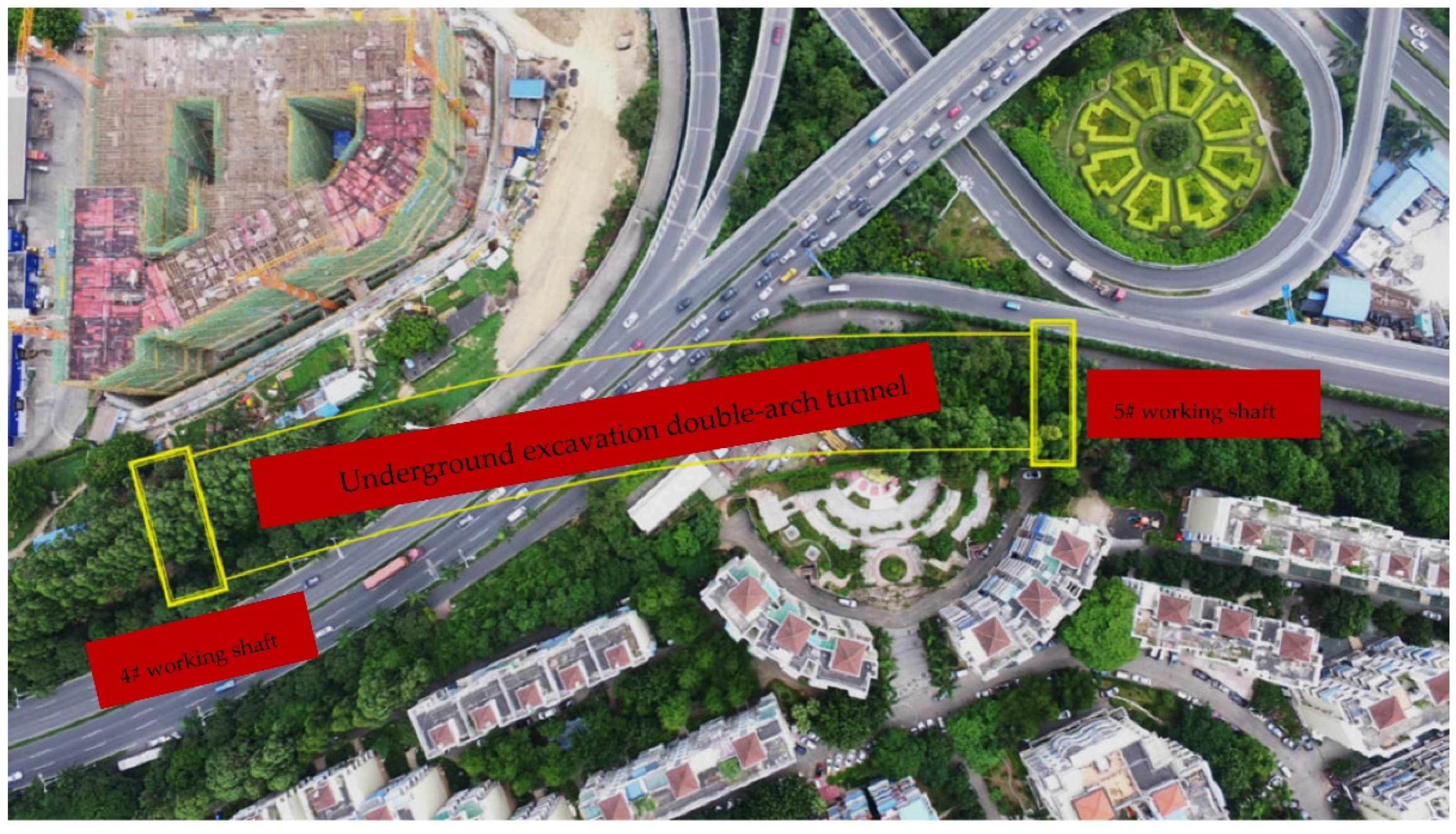
2. Overview of the Engineering
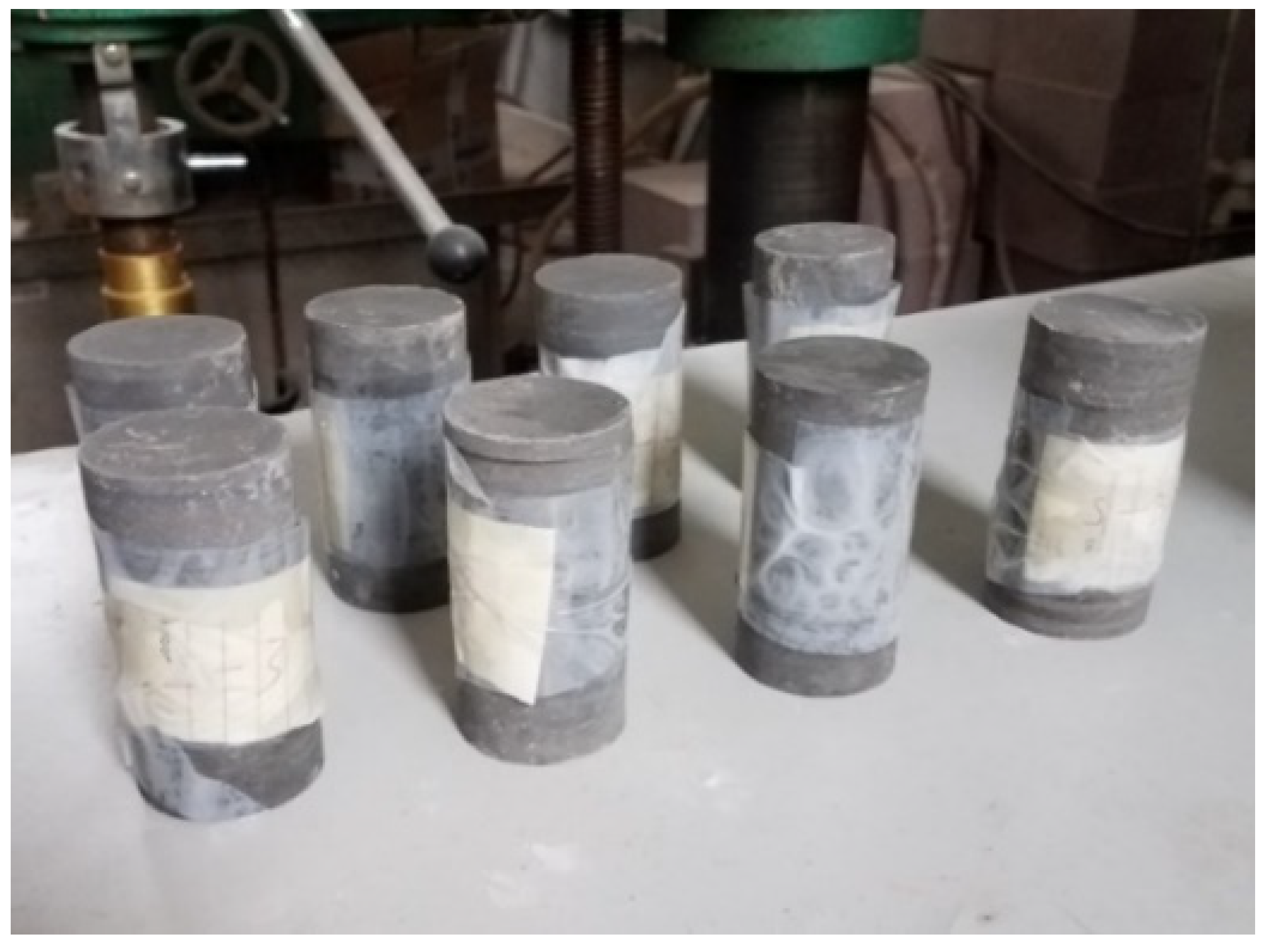
The double-arch tunnel of Haicang tunnel is located in Huli District, **, the mold top cover was installed and the test piece was manually pressurized into a cylindrical specimen with a height of 100 mm and a diameter of 50 mm. After standing for 30 min at room temperature, the specimen was demolded. The error of specimen height and diameter was controlled within 0.3 mm, the maximum error of non-parallelism of both ends of the specimen was controlled within 0.05 mm, the end surface was perpendicular to the axis, and the maximum error did not exceed 0.25 mm. The samples were cured for 7 days around 20 °C under natural drying conditions.
Figure 3 shows the sample. To provide a reasonable grouting ratio for tunnel grouting construction and to obtain a better grouting reinforcement effect, the grouting reinforcement effect was evaluated under different water–cement ratios on the basis of the slurry fluidity, setting time, bleeding rate, and strength of the sample.
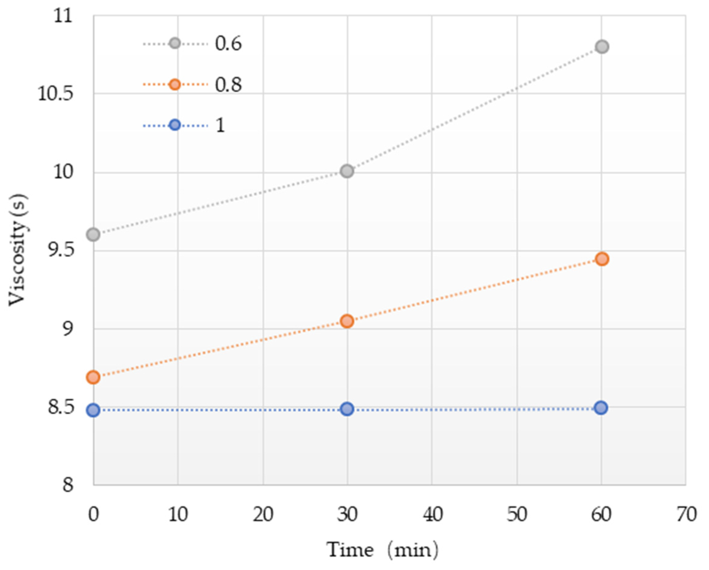
The fluidity of the slurry reflected the viscosity of the slurry. The greater the viscosity, the longer it took to inject into a certain position of the soil. The lower the viscosity, the stronger the fluidity of the slurry, and the grouting time can be shortened during the grouting process and the grouting efficiency can be improved.
Figure 4 shows the fluidity test results of cement slurry. The viscosity of cement slurry decreased with the increasing water–cement ratio. When the water–cement ratio increased from 0.6 to 1, the initial viscosity of cement slurry decreased from 9.6 s to 8.48 s, which is a decrease of 1.12 s. At 30 min, the viscosity decreased from 10.01 s to 8.48 s, which is a decrease of 1.53 s. The 60 min viscosity decreased from 10.8 s to 8.49 s, which is a decrease of 2.31 s. Additionally, the viscosity of cement slurry increased gradually under different water–cement ratio; the smaller the water–cement ratio was, the faster the viscosity increased. When the water–cement ratio was 1, the viscosity remained basically unchanged with time.
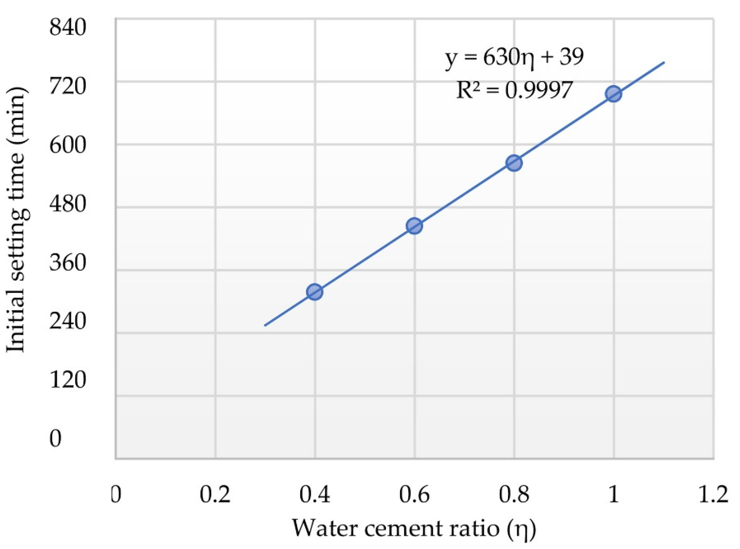
Figure 5 shows the relationship between water–cement ratio and initial setting time. The initial setting time of cement slurry basically increased linearly with the increasing water–cement ratio. When the water–cement ratio was 0.4, the initial setting time of cement slurry was 318 min, and when the water–cement ratio increased to 1.0, the initial setting time increased to 696 min, an increase of about 1.2 times. According to the test results, the relationship between water–cement ratio and initial setting time of cement slurry was fitted, and the following was obtained:
where y refers to the initial setting time of cement slurry (min) and η refers to the water–cement ratio of water slurry. The correlation coefficient R
2 of the fitting result was 0.9997, which shows that the fitting result was good.
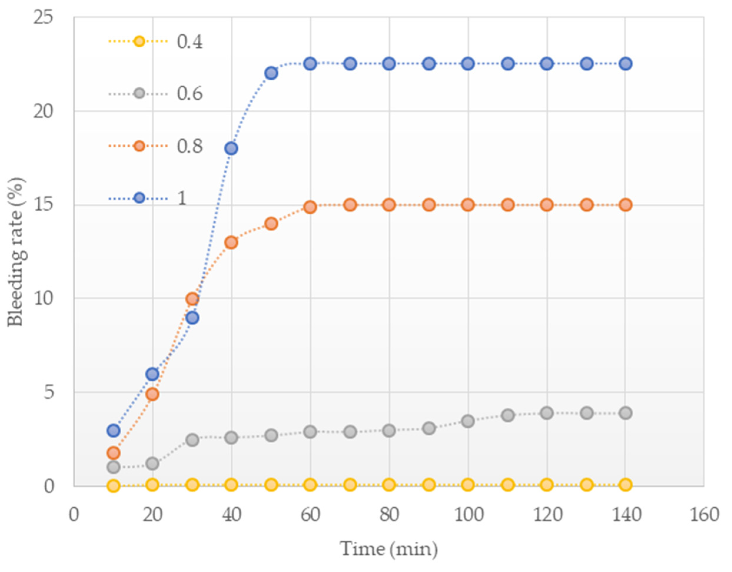
Cement and water were fully mixed to form a cement slurry. After standing for a period of time, a part of free water precipitated out of it. The phenomenon is called bleeding, which is related to the stability of the slurry.
Figure 6 shows the bleeding rate of the cement slurry in the test. The bleeding rate of the slurries with different water cement ratios gradually increased to a certain value over time and then became stable, and the larger the water–cement ratio, the greater the bleeding rate of the slurry. When the water–cement ratio increased from 0.4 to 1, the bleeding rate increased from 0.1% to 22.5% at 140 min, an increase of 22.4%, and the bleeding rate reached a stable level at about 50 min. When the water–cement ratio was 0.4, the bleeding rate was always maintained at 0.1%, indicating that the sample almost did not separate water. When the water–cement ratio was 0.6, the bleeding rate increased from 1% to 3.9% at 140 min. When the water–cement ratio was 0.8, the bleeding rate increased from 1.8% to 15% at 140 min. When the water cement ratio was 1, the bleeding rate increased from 3% to 22.5% at 140 min, indicating that the sample had strong water separation.
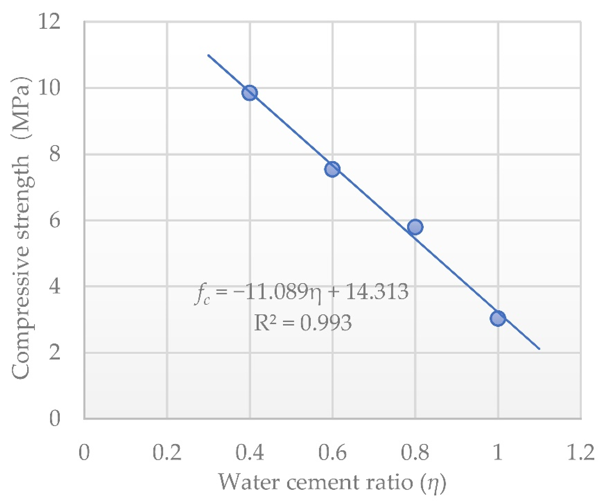
Figure 7 shows the compressive strength of cement samples under different water–cement ratios. The sample strength decreased linearly with the increasing water–cement ratio. When the water–cement ratio increased from 0.4 to 1.0, the strength decreased from 9.8 MPa to 3 MPa, which decreased by about 30.6%. The fitting relationship between strength and water–cement ratio is shown below:
where
fc is the strength of the cement sample (MPa), and η is the water–cement ratio. The correlation coefficient R
2 of the fitting result was 0.993. Thus, the fitting result was good.
The water–cement ratio has different effects on the viscosity, bleeding rate, and initial setting time of cement slurry, and the reasonable water–cement ratio cannot be determined only by experiments—the influence of onsite conditions should be considered. To obtain a reasonable water–cement ratio, further numerical simulation research was performed.
3.2. Grouted Surrounding Rock Strength
The mechanical behavior of rock and soil conformed to the Mohr–Coulomb failure criterion, and the main grouting and solid strength parameters were the friction angle
φ and the cohesive force c. The grouted surrounding rock strength has a great relationship with the strength of the rock mass before grouting, the strength of the grout stone body, grouting pressure, and time. When the grouting pressure and time met the specification requirements, the strength of rock and soil before grouting was the main influencing factor. The UCS of rock and soil before grouting, water–cement ratio, and strength of rock and soil after grouting reinforcement were obtained from references [
34,
35,
36,
37,
38,
39,
40,
41], combined with the relationship between rock mass UCS parameters and shear strength parameters (3) and (4), the friction angle
φ and cohesion c increase rate of grouted surrounding rock were obtained.
Table 1 shows the statistical results.
where
,
and
are the increase rate of cohesive force
c (%), friction angle
φ (%) and UCS (%), respectively.
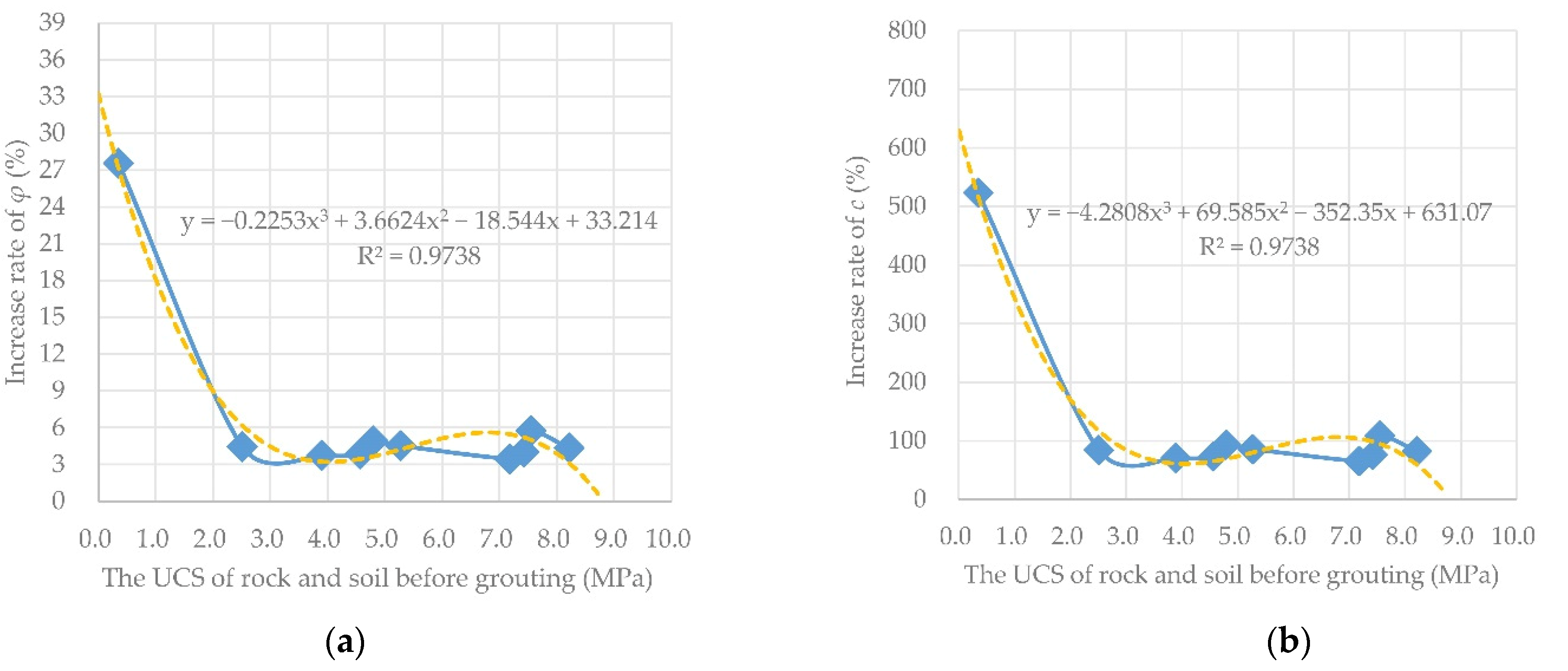
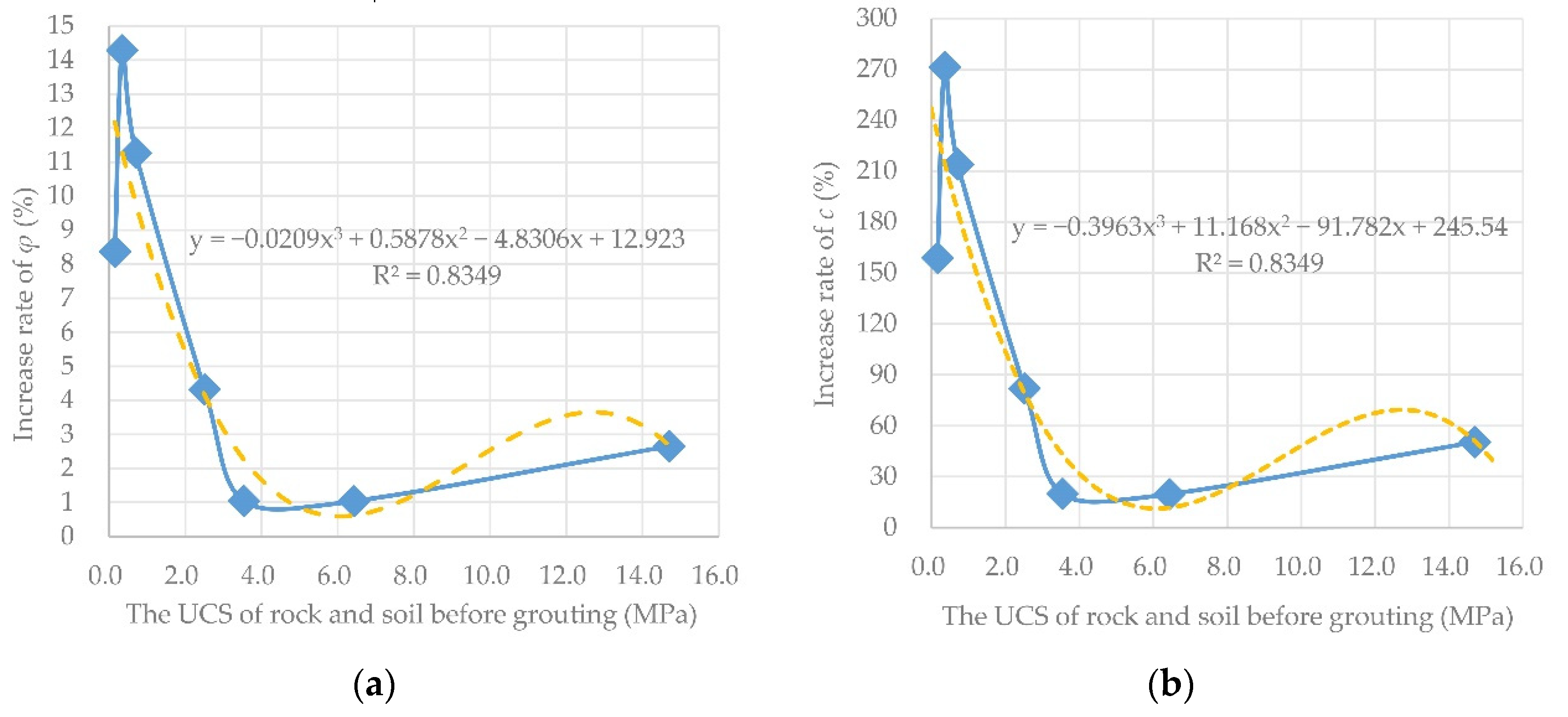
The data in
Table 1 are plotted in
Figure 8 and
Figure 9. The relationship between the UCS of rock and soil before grouting and the shear strength parameter increase rate of rock and soil after grouting were obtained by curve fitting when the water–cement ratio η of the grout was 0.75 and 1.0. The distribution of the data has certain regularity. The cubic polynomial was used to fit the limited data corresponding to the slurry water–cement ratio η = 0.75 and η = 1.0, and the fitting correlation coefficients R
2 were 0.9738 and 0.8349, respectively, indicating that the model fitting effect was good. The UCS, internal friction angle, and cohesion of the rock and soil before grouting in the construction area were determined according to geological survey data or laboratory experiments. The shear strength parameters of rock mass under different grouting reinforcement were calculated. According to the detailed survey report of Haicang Tunnel, the UCS of the surrounding rock before grouting within the tunnel excavation range was 0.108 MPa, the internal friction angle
φ = 20°, and the cohesive force
c = 0.06 MPa. Substituting the unconfined compressive strength into the fitting curve formulas of
Figure 8 and
Figure 9, the shear strength increase rates of the rock and soil mass were obtained as
,
,
, and
. According to the shear strength increase rate, the internal friction angle
φ = 20.28° and the cohesion force
c = 0.4179 MPa when the water–cement ratio η = 0.75. Similarly, the internal friction angle
φ = 22.49° and cohesion force
c = 0.2019 MPa when the water–cement ratio η = 1.
The influence of slurry water–cement ratio variation on the strength of grouted surrounding rock was analyzed. The deformation of the surrounding rock and the stability of the tunnel, the corresponding rock mass shear strength parameter when the water–cement ratio was 0.8, 0.85, 0.9, and 0.95 were obtained by interpolation (
Table 2).
5. Conclusions
To study the reasonable grouting thickness and water–cement ratio of the surrounding rock of the double arch tunnel in the Haicang Tunnel, the ground settlement, deformation of the vault, and adjacent pipeline under different grouting parameters were studied through laboratory tests, literature analysis, and numerical simulation. The following conclusions were obtained.
(1) The viscosity of cement slurry decreased with the increase of water–cement ratio. The initial setting time of cement slurry increased linearly with the increasing water–cement ratio. The slurry bleeding rate gradually increased with time and tended to be stable after reaching a certain value, and the greater the water–cement ratio, the greater the slurry bleeding rate. The strength of the sample decreased linearly with the increase of the water cement ratio.
(2) Frictional angle φ and cohesive force c can be determined by water–cement ratio of slurry and UCS of rock mass before grouting.
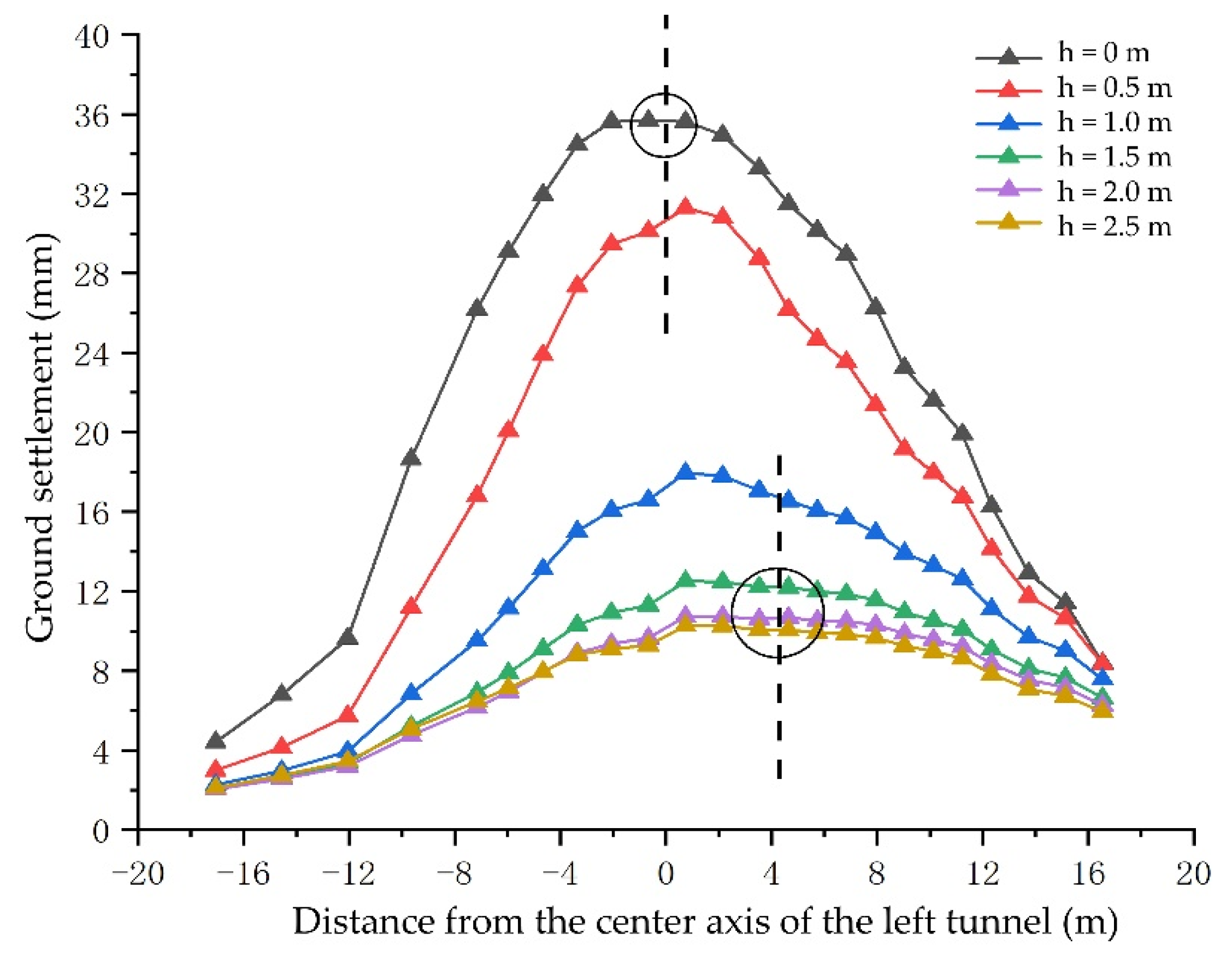
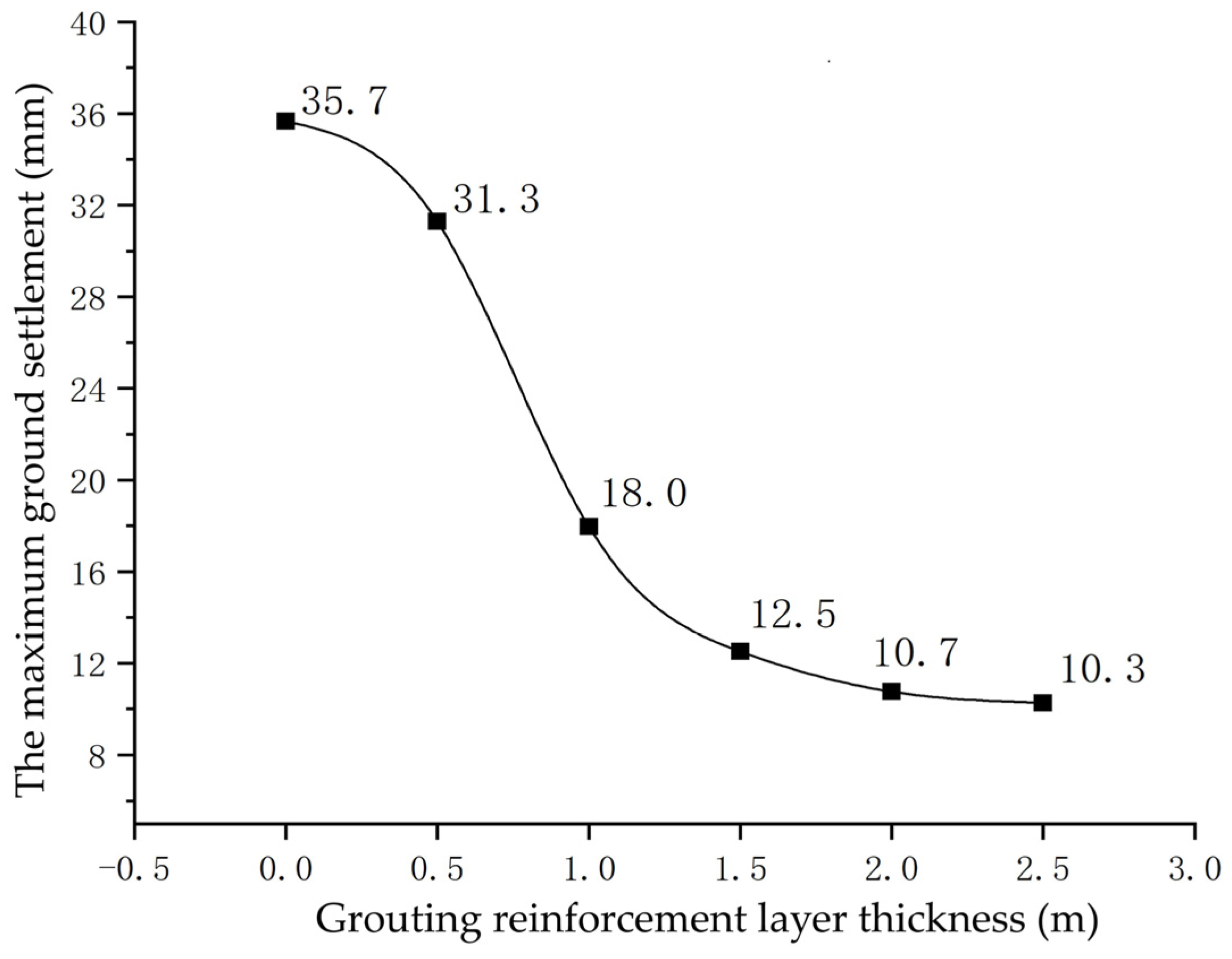
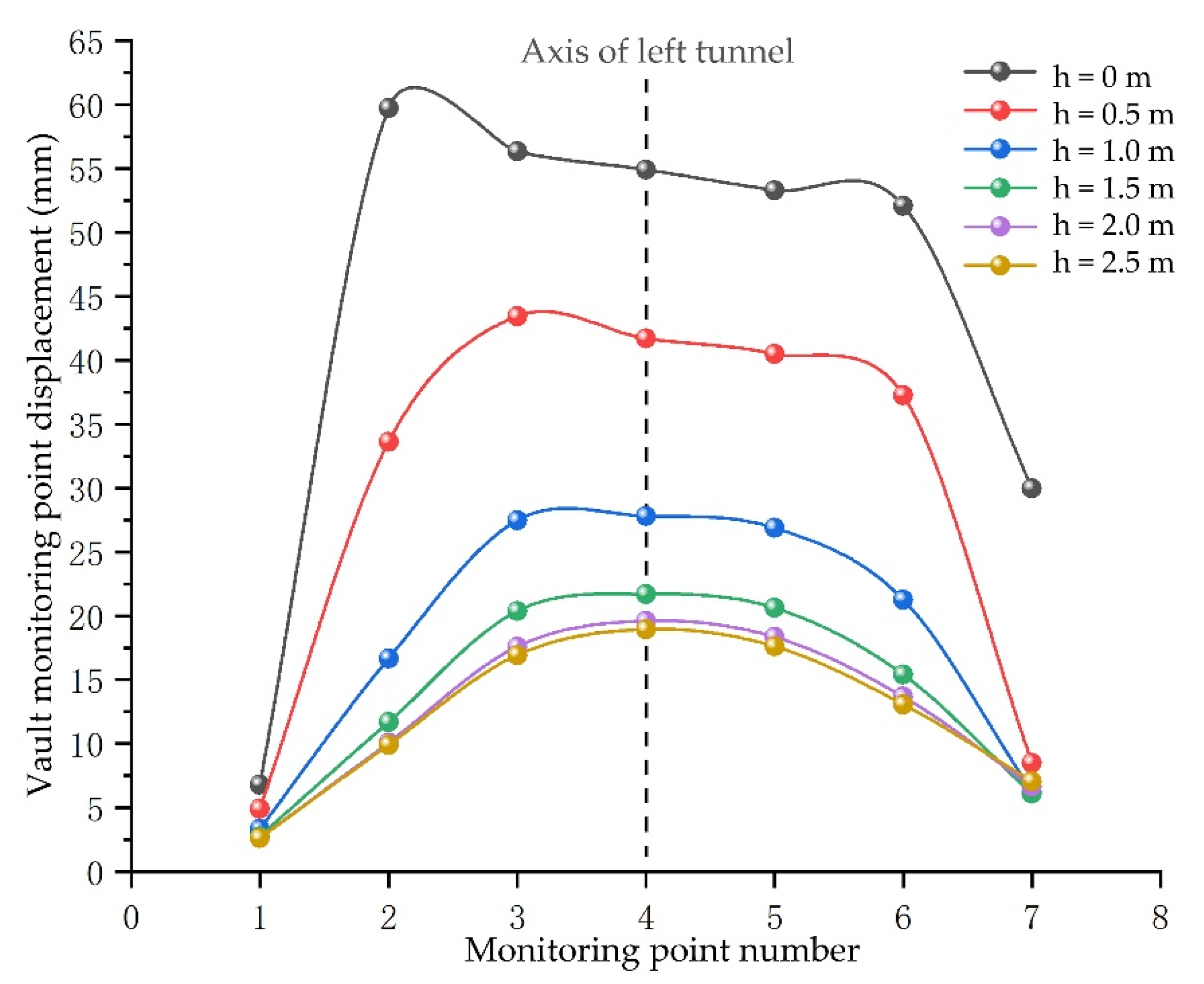
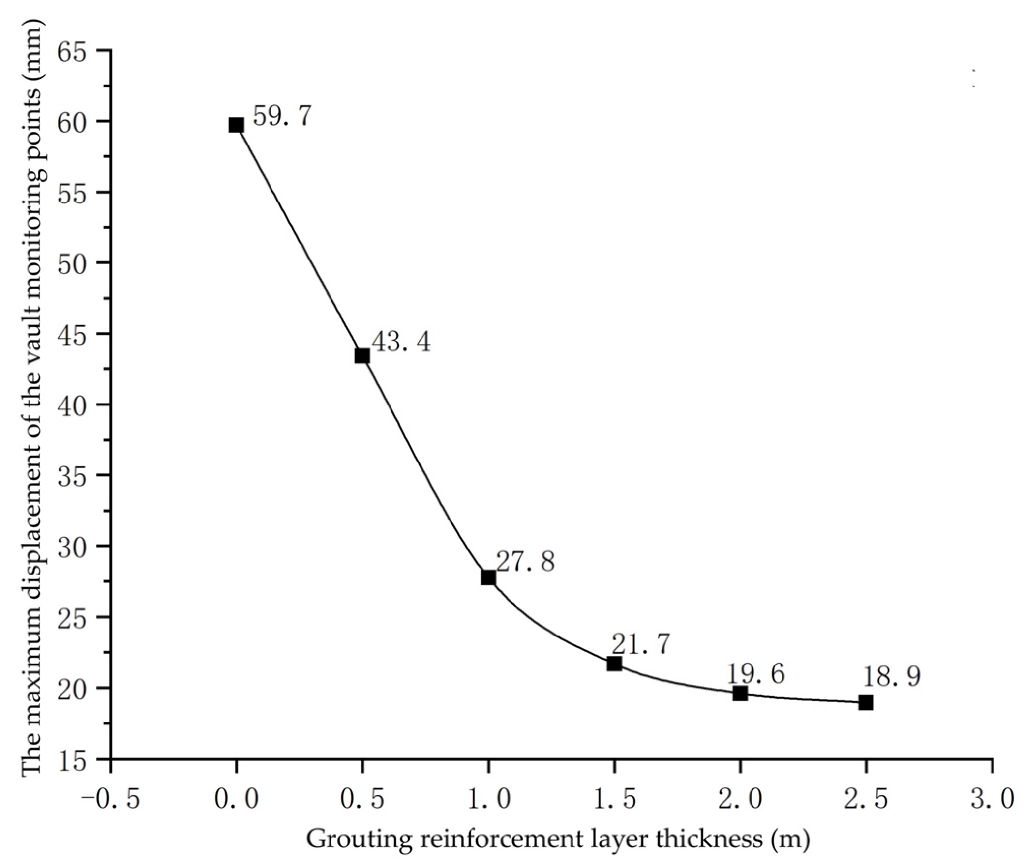
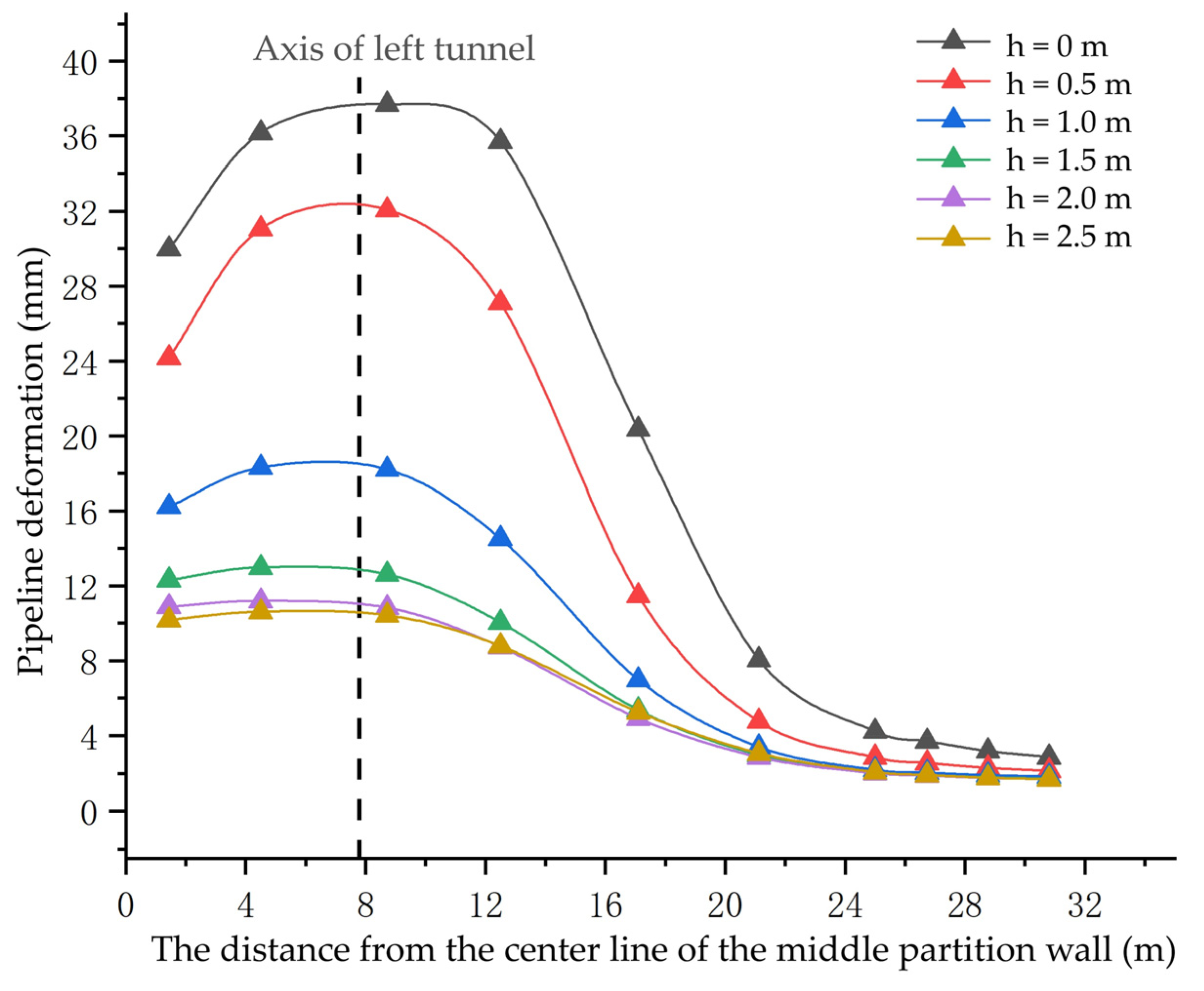
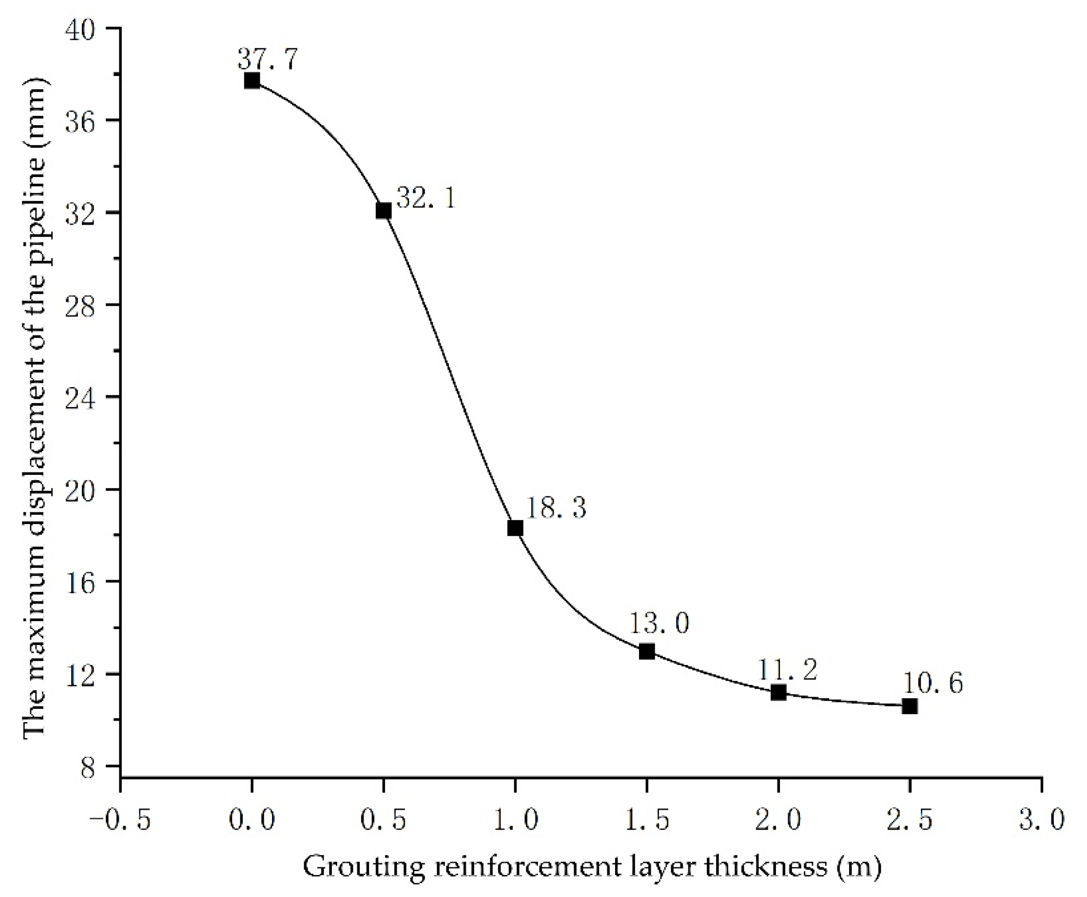
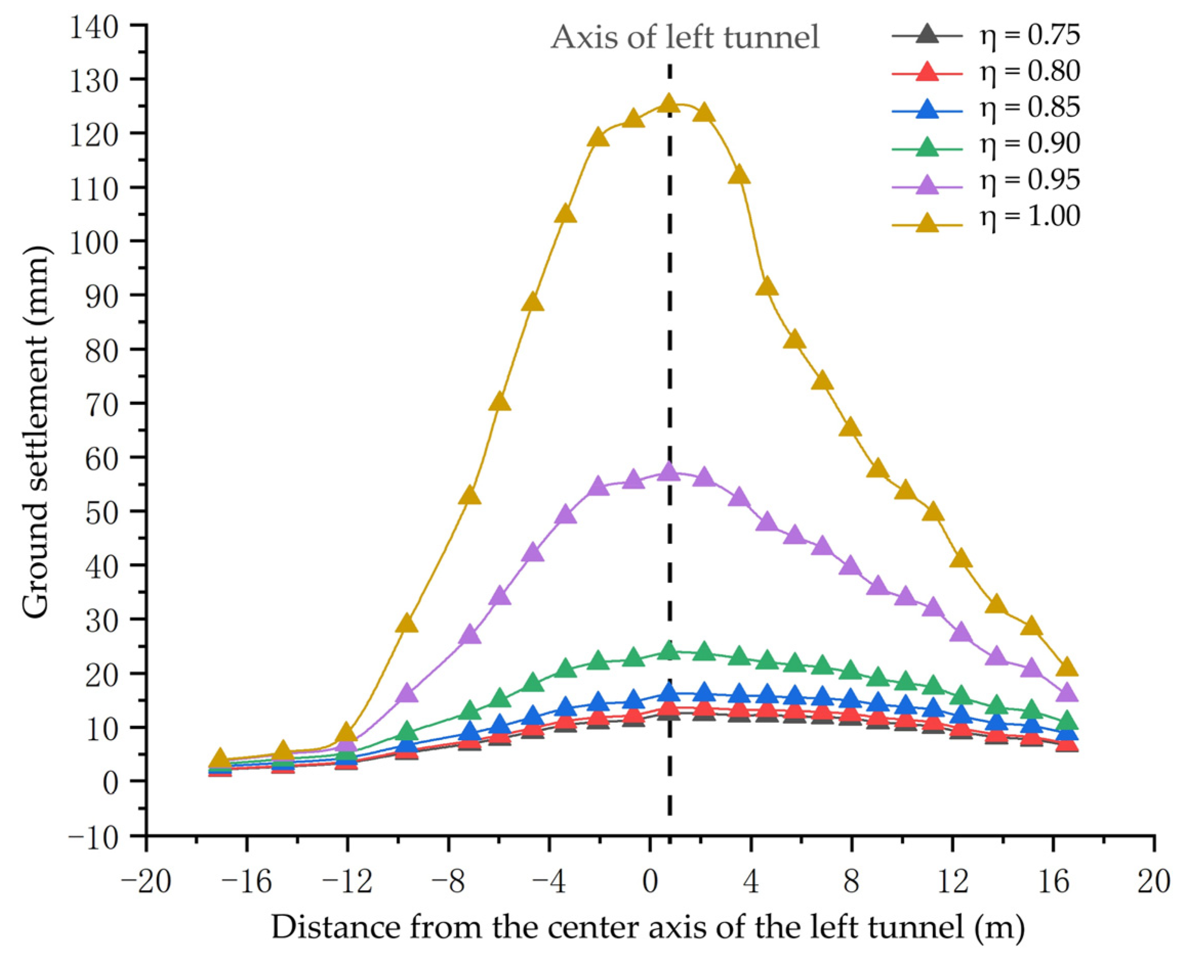
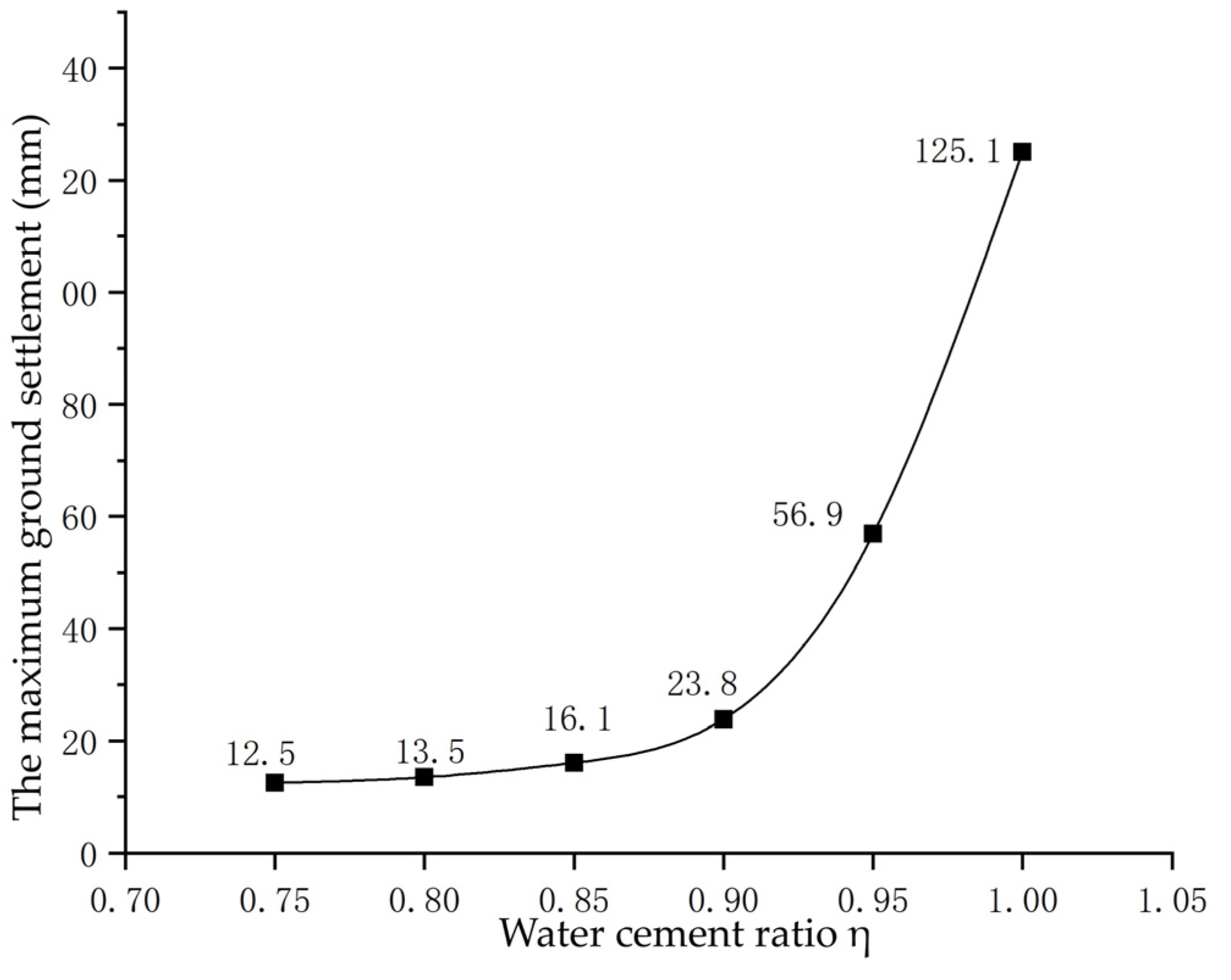
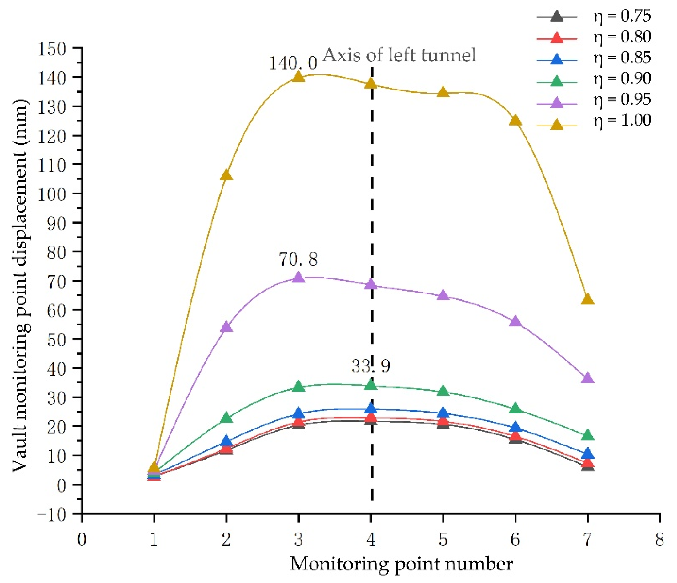
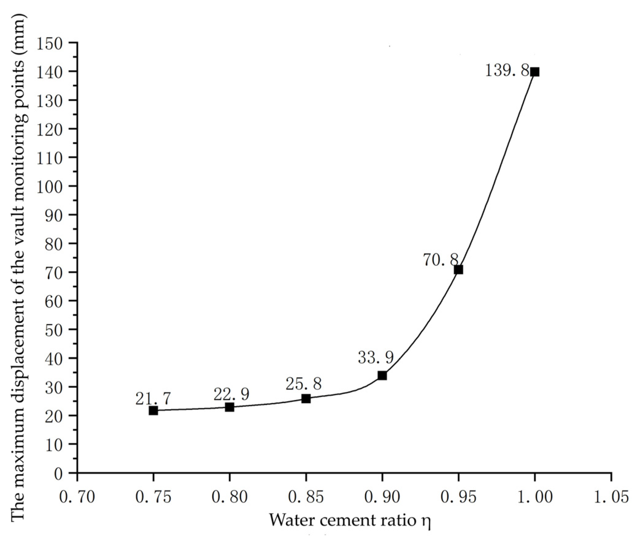
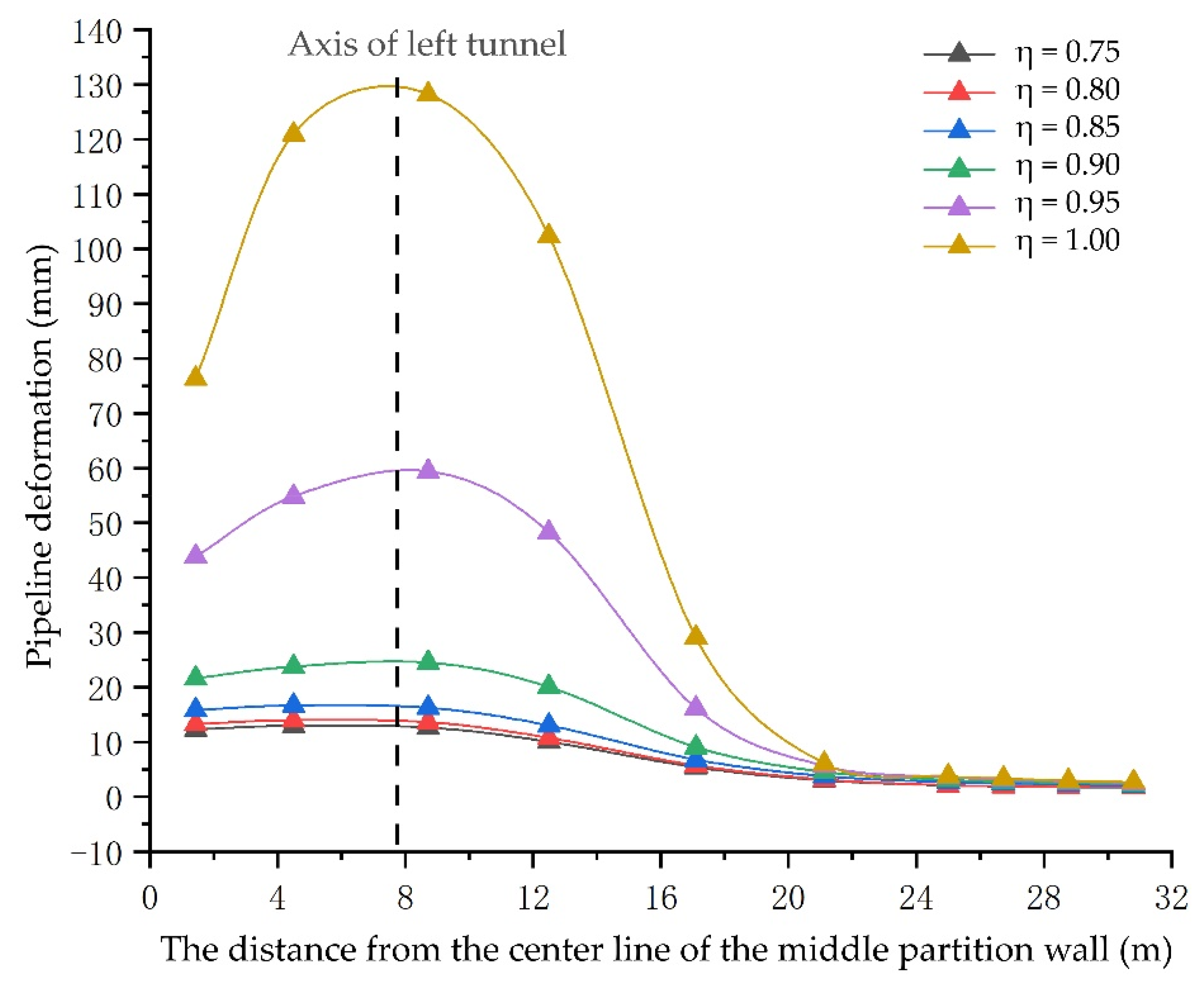
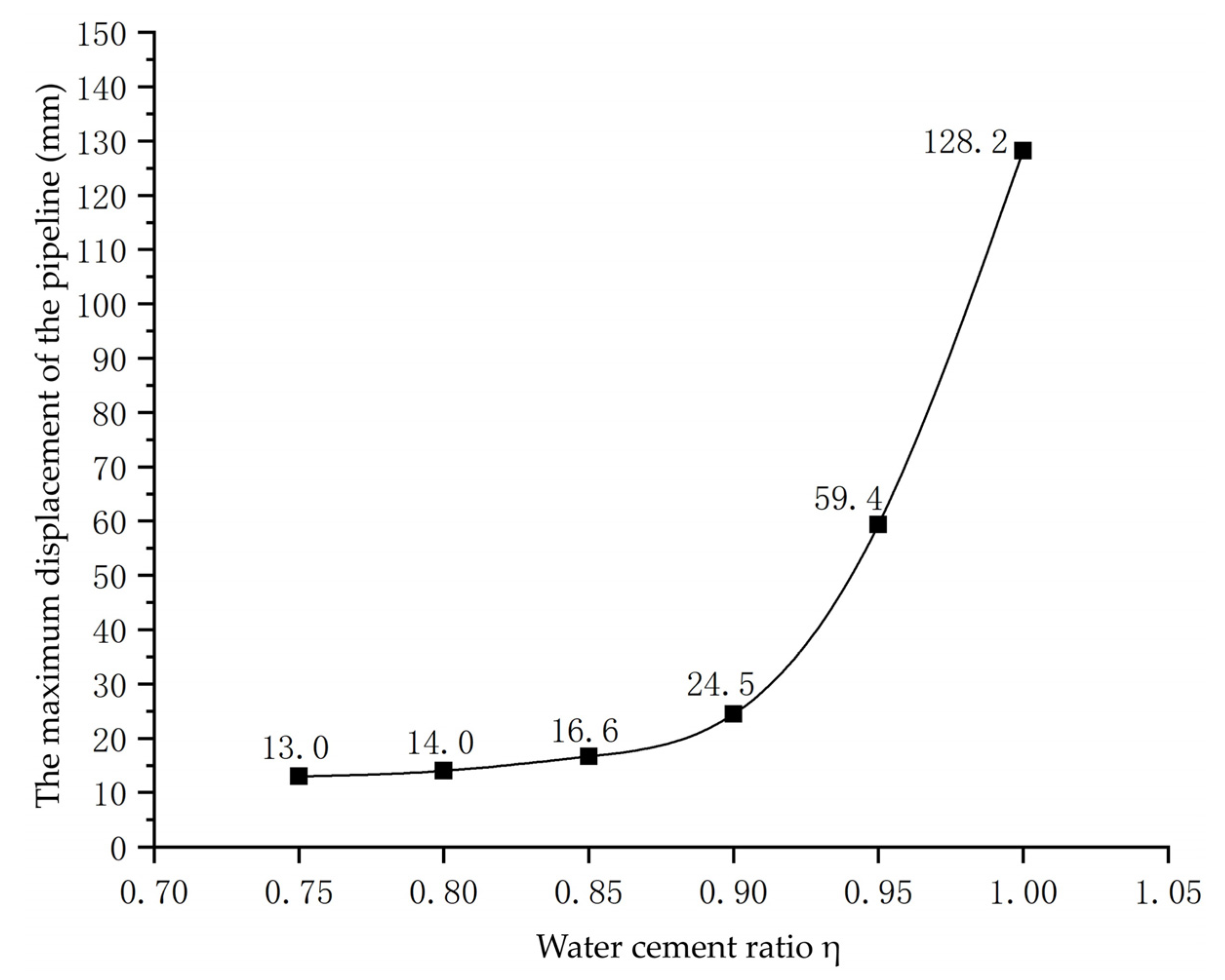
(3) With the increase of reinforcement layer thickness and the decrease of cement slurry water–cement ratio, the ground settlement, vault displacement, plastic zone area, and pipeline deformation continued to decrease, but the reduction range increased first and then decreased.
(4) When the grouting reinforcement layer thickness h = 1.5 m and the water–cement ratio η = 0.85, the tunnel grouting reinforcement effect was best and more economical.


 ,
, 


