
Research on Stability Evaluation of Perilous Rock on Soil Slope Based on Natural Vibration Frequency


Abstract
:1. Introduction
2. Materials and Methods
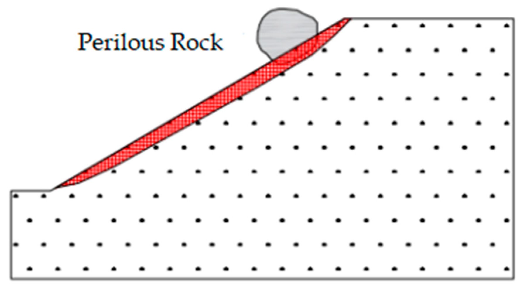
2.1. Perilous Rock on Soil Slope and Research Method
2.2. Dynamic Characteristic Model of Perilous Rock on Soil Slope
3. Model Test
3.1. Test Equipment
- (1)
- Vibration meterSpecifically, a Microchip Cube wireless vibrometer manufactured by Bei**g Beike Andi Technology Development Co., Ltd. (Bei**g, China) was used in the experiment with a quick sampling rate, a high signal-to-noise ratio, and wireless data transmission. The frequency of the object’s natural vibrations in all three dimensions was determined using the Fourier transform. The exact vibration meter parameters are depicted in Table 1.
- (2)
- Vibration measurementWe attached the vibration detector to the model’s summit and then used epoxy glue to connect the detector’s fixed plate to the perilous rock block shown in the foreground. The installation of the layout sensor occurred after the epoxy resin had dried and the test model had been taken entirely. The velocity/acceleration in the three dimensions was activated after the hammer excited the wide frequency domain, measuring the object’s time-domain representation in Figure 3. After obtaining a representation of the observed object’s frequency domain by filtering and the Fourier transform (Figure 4), the measured object’s natural vibration frequency could be determined.
3.2. Experimental Model
- (1)
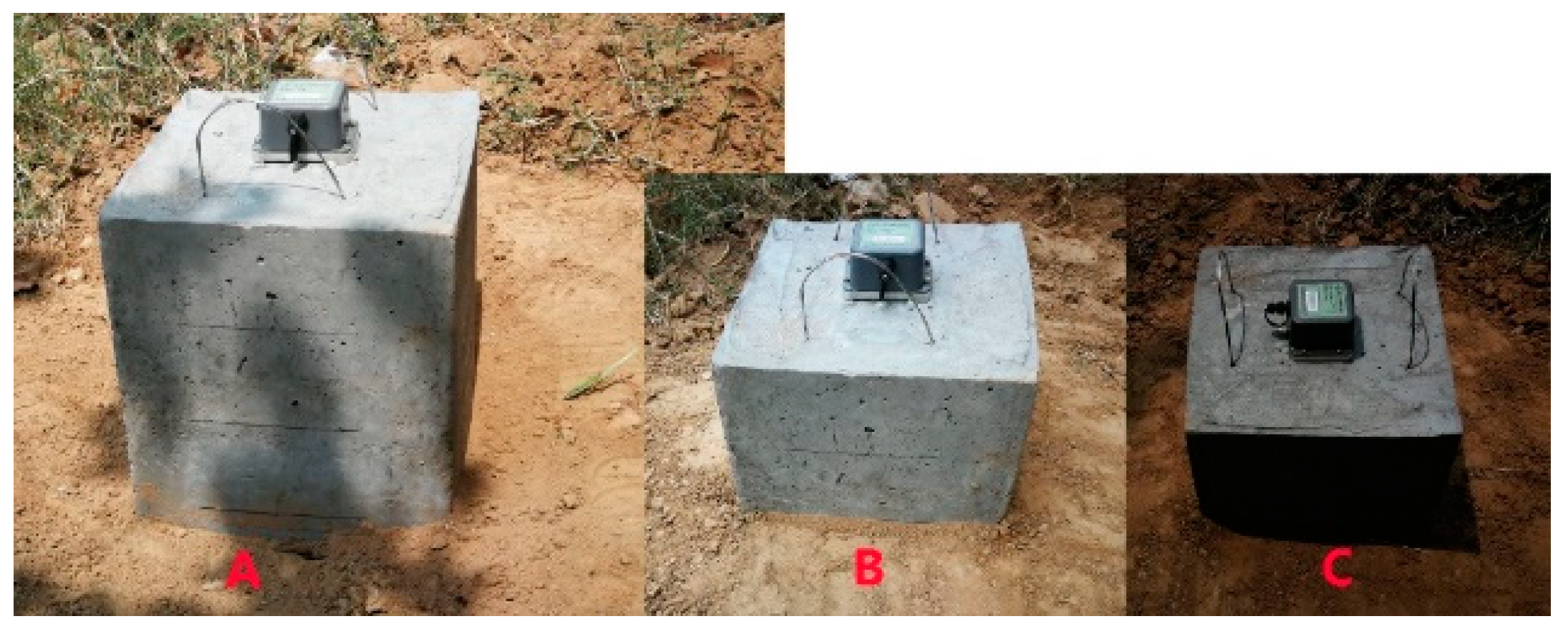
- Test modelIn the experiment, cubes of different sizes and qualities were used to simulate perilous rocks. The dimensions of models A, B, and C were 0.3 m × 0.3 m × 0.4 m, 0.3 m × 0.3 m × 0.3 m, and 0.3 m × 0.3 m × 0.2 m, respectively, and the masses were 84.3 kg, 63.2 kg, and 42.5 kg, respectively. Figure 5 depicts the experiment’s perilous rock model.
- (2)
- Foundation soilWe took the soil on the open-top landslide body on the Dadu River National Road slope as the test foundation soil. The natural density, natural dry density, deformation modulus, and grain group content of the soil were obtained through conventional soil tests. Table 2 displays the standard properties of the foundation soil.
3.3. Test Plan
3.4. Test Results
3.5. Discussion
- (1)
- Correlation between the buried depth of the perilous rock and the natural vibration frequency.
- (2)
- Relationship between the natural vibration frequency and the perilous rock mass.
4. Perilous Rock Stability Evaluation
4.1. Force Analysis of Perilous Rock
4.2. Stability Evaluation Model
4.3. Example
Author Contributions
Funding
Institutional Review Board Statement
Informed Consent Statement
Data Availability Statement
Conflicts of Interest
References
- Hung, W.-Y.; Tran, M.-C.; Yeh, F.-H.; Lu, C.-W.; Ge, L. Centrifuge modeling of failure behaviors of sandy slope caused by gravity, rainfall, and base shaking. Eng. Geol. 2020, 271, 105609. [Google Scholar] [CrossRef]
- Zhang, W.-G.; Meng, F.-S.; Chen, F.-Y.; Liu, H.-L. Effects of spatial variability of weak layer and seismic randomness on rock slope stability and reliability analysis. Soil Dyn. Earthq. Eng. 2021, 146, 106735. [Google Scholar] [CrossRef]
- Pan, Y.; Wu, G.; Zhao, Z.; He, L. Analysis of rock slope stability under rainfall conditions considering the water-induced weakening of rock. Comput. Geotech. 2020, 128, 103806. [Google Scholar] [CrossRef]
- Romeo, S.; Di Matteo, L.; Melelli, L.; Cencetti, C.; Dragoni, W.; Fredduzzi, A. Seismic-induced rockfalls and landslide dam following the October 30, 2016 earthquake in Central Italy. Landslides 2017, 14, 1457–1465. [Google Scholar] [CrossRef]
- He, S.M.; Shen, J.; Wu, Y. Rock shed dynamic response to impact of rock-fall. Rock Soil Mech. 2011, 32, 781–788. [Google Scholar]
- Cappadonia, C.; Cafiso, F.; Ferraro, R.; Martinello, C.; Rotigliano, E. Rockfall hazards of Mount Pellegrino area (Sicily, Southern Italy). J. Maps 2021, 17, 29–39. [Google Scholar] [CrossRef]
- Jacklitch, C.; Shakoor, A.; Lund, W.R. Evaluation of Rockfall-Hazard Potential for Rockville, Utah, Following a 2013 Fatal Rockfall. Environ. Eng. Geosci. 2018, 24, 143–163. [Google Scholar] [CrossRef]
- Zhang, J.; Liang, Z.; Feng, D.; Zhang, C.; ** dangerous rock structural surface based on dynamic characteristic parameters. Front. Earth Sci. 2022, 10, 942025. [Google Scholar] [CrossRef]
- Zhang, W.; He, Y.; Wang, L.; Liu, S.; Meng, X. Landslide Susceptibility Map** Using Random Forest and Extreme Gradient Boosting: A Case Study of Fengjie, Chongqing. Geol. J. 2023. [Google Scholar] [CrossRef]
- Liu, S.; Wang, L.; Zhang, W.; He, Y.; Pijush, S. A comprehensive review of machine learning-based methods in landslide susceptibility map**. Geol. J. 2023. [Google Scholar] [CrossRef]


| Parameter | Minimum | Maximum | Unit |
|---|---|---|---|
| range | −5.0 | +5.0 | |
| sampling ratio | 5.0 | 800 | |
| resolution | 0.50 | — |
| Test Factor | Average | Unit |
|---|---|---|
| natural density () | 1.92 | g/cm3 |
| internal friction angle () | 20.0 | ° |
| coefficient of subgrade reaction (k) | 6.5 × 10⁴ | kN/m3 |
| cohesion (C) | 7.0 | kN/m2 |
| Models | Buried Depth/cm | Measured Frequency/Hz | Buried Depth Calculation/cm | Error/% |
|---|---|---|---|---|
| A | 8 | 13.6 | 7.49 | 6.37% |
| A | 16 | 23.2 | 16.72 | 4.51% |
| A | 24 | 31.8 | 24.61 | 2.52% |
| A | 32 | 39.2 | 31.18 | 2.56% |
| B | 6 | 16.5 | 6.34 | 5.69% |
| B | 12 | 25.3 | 12.36 | 3.03% |
| B | 18 | 32.6 | 17.51 | 2.73% |
| B | 24 | 39.9 | 23.51 | 2.02% |
| C | 4 | 17.7 | 3.84 | 3.92% |
| C | 8 | 27.4 | 8.32 | 3.97% |
| C | 12 | 35.4 | 12.82 | 6.83% |
| C | 16 | 40.9 | 16.26 | 1.63% |
| Length of Perilous Rock | /cm | Width/cm | Height/cm | Mass/kg | Slope Angle/° |
|---|---|---|---|---|---|
| A | 3.33 | 5.21 | 7.23 | 327,386.50 | 25.00 |
| B | 2.85 | 4.89 | 4.56 | 165,866.65 | 25.00 |
Disclaimer/Publisher’s Note: The statements, opinions and data contained in all publications are solely those of the individual author(s) and contributor(s) and not of MDPI and/or the editor(s). MDPI and/or the editor(s) disclaim responsibility for any injury to people or property resulting from any ideas, methods, instructions or products referred to in the content. |
© 2023 by the authors. Licensee MDPI, Basel, Switzerland. This article is an open access article distributed under the terms and conditions of the Creative Commons Attribution (CC BY) license (https://creativecommons.org/licenses/by/4.0/).
Share and Cite
Jia, Y.; Song, G.; Wang, L.; Jiang, T.; Zhao, J.; Li, Z. Research on Stability Evaluation of Perilous Rock on Soil Slope Based on Natural Vibration Frequency. Appl. Sci. 2023, 13, 2406. https://doi.org/10.3390/app13042406
Jia Y, Song G, Wang L, Jiang T, Zhao J, Li Z. Research on Stability Evaluation of Perilous Rock on Soil Slope Based on Natural Vibration Frequency. Applied Sciences. 2023; 13(4):2406. https://doi.org/10.3390/app13042406
Chicago/Turabian StyleJia, Yanchang, Guihao Song, Luqi Wang, Tong Jiang, **di Zhao, and Zhanhui Li. 2023. "Research on Stability Evaluation of Perilous Rock on Soil Slope Based on Natural Vibration Frequency" Applied Sciences 13, no. 4: 2406. https://doi.org/10.3390/app13042406