1. Introduction
In the United States, more than 795,000 people are affected by a stroke annually [
1,
2,
3]. Stroke is one of the most devastating of all neurological diseases due to its tendency to leave patients with a physical impairment or disability [
4]. Many more patients lose hand–motor function due to certain cancers [
5,
6], various neuromuscular disorders and injuries [
7,
8]. Hand–motor function impairment ultimately has a profound effect on the affected person’s ability to perform even the most fundamental daily tasks [
9,
10,
11]. Rehabilitation after a stroke or injury is essential to regaining maximum mobility of the affected limbs [
12,
13,
14]. The standard rehabilitation process requires patients to perform a repetitive exercise routine in order to regain some of the previous motor functions [
15,
16]. These therapy regimens involve a large amount of patient–therapist interaction time, thus substantially raising the cost of treatment.
Robotics have been proven to be successful in assisting a patient’s progress in the rehabilitation process [
17,
18,
19,
20,
21,
22]. The human hand is a complex mechanical device with 19 bones, 14 joints and over 25 degrees of freedom [
23]. Due to this mechanical complexity, most of the studies done in the field of rehabilitation robotics have focused on regaining upper-limb mobility [
24,
25,
26,
27,
28,
29] with less focus on robotic rehabilitation techniques of the hand and fingers [
23]. The construction and actuation methods used in current robotic exoskeleton technologies generally result in expensive, bulky and physically confining devices. Due to the cost and size of these devices, robotic-aided therapy can only be implemented during appointments with a physical therapist. Frequent visits, which are key to the success of the therapy regimen, may not be feasible for many patients due to their financial situation, location or other constraints.
Construction of a robotic hand exoskeleton presents a unique design challenge due to the extreme complexity and small size of the human hand. The size of modern actuators makes it infeasible to actively control each degree of freedom individually, leading researchers in the field to focus on under-actuated mechanisms. These under-actuated mechanisms must be connected to a structure that is compact and light enough to fit on the human hand, while still allowing for natural motion of the fingers. Heo et.al. [
23] define six methods for the construction of both rigid and non-rigid structures for robotic finger manipulation and provide details about common actuation systems seen in the field of hand rehabilitation robotics. The most common method of actuation involves the use of an under-actuated serial link superstructure fixed to a point on either the middle or distal phalange to control the flexion of the finger. While rigid-link manipulators provide excellent control and repeatability of motion, they are mechanically complex and require customization to align the manipulator joints to the finger joints. Two methods are shown where no rigid-link mechanical structure is required to facilitate actuation; tendon-driven mechanisms and flexible actuators.
The Hand of Hope [
30] and Festo Exohand [
31] are two commercially available systems that utilize serial link manipulators to actuate fingers. The Hand of Hope was one of the first commercially available robotic hand rehabilitation mechanisms. While the Hand of Hope is a mechanically sound device, the limited range of motion in the metacarpophalangeal (MCP) and proximal interphalangeal (PIP) joints and the non-customizable nature of the design leave room for improvement. The Festo Exo-Hand [
31] shows much improvement in these areas, due to user-specific dimensioning using 3D scanners and a laser sintering process. Improvement is also seen in the range of motion as well as the number of degrees of freedom controlled by the device. This improvement is achieved using eight proprietary pneumatic actuators. These improvements come at a cost. The user must be linked to a compressed air source through a bulky umbilical of pneumatic hoses, thus restricting mobility. The customization of each device, while favorable, is very expensive in both time and cost.
The Whitesides group [
32] developed a robotic exoskeleton using custom-designed, naturally compliant soft actuators. This design utilizes custom molded, hydraulically controlled actuators created from a soft silicone rubber compound reinforced with mesh. The design is very low profile and light weight, weighing in at 285 g. However, the hydraulic pump system, weighing over 3 kg, must be attached to the patient for untethered use. The customizability of the exoskeleton, while desirable, poses the same time and cost issues as the serial link devices presented earlier.
Academic research groups such as Martinez et al. [
33] and HyunKi In et al. [
34] have focused on develo** tendon-driven systems that makes use of power-actuated tendons for adduction and a passive spring mechanism for abduction. Martinez et al. [
33] incorporate a rigid exoskeleton to constrain joint motion, which is customizable using sliding linkages between joints and oversized rings to secure the structure to the finger, this design incorporates many of our desired features, but the use of a rigid exoskeleton adds unnecessary bulk and complicates the design of the system. HyunKi In et al. [
9] focused their research on the development of a jointless structure to facilitate the implementation of their tendon-driven actuation method. The described jointless structure passes the tendons through channels sewn into the palmar side of a soft glove, while a semi-rigid material provides a passive extension force.
The jointless design and tendon-driven method of actuation corresponds closely to the method we envisioned for our design. The rigid serial link method utilized in the Hand of Hope and Festo Exohand discussed earlier provides an excellent kinematic response and repeatability, but this actuation method requires hardware much too complicated for the end user to assemble and customize on their own [
30,
31]. Tendon-driven actuation greatly simplifies the mechanical structure and thus is our chosen method of actuation. The previously presented designs that use this method, while simple in mechanical design, incorporate complicated custom electronics and control systems designed solely for academic pursuits. Our design aims to simplify the mechanical structure, electronics and control system to provide a system that can be easily assembled, customized and controlled by the end user.
The Whitesides group [
35] present a soft pneumatic glove for hand rehabilitation fabricated using soft robotic technology. The soft actuators are made of elastomeric materials with integrated channels that function as pneumatic networks (PneuNets) which can be driven by air pressurization to produce bending motions in conformity with human fingers. The PneuNets approach to air-driven actuation is an alternative to fluidic McKibben actuators, which are compliant actuators based around a rubber tube surrounded by a braided shell. The group successfully shows that PneuNets can be embedded into a neoprene glove to enable a similar therapy modality as our approach, the difference being that the fabrication method they present is not easily accessible by a layperson and that the resulting glove would have to be tethered to a bulky air compression system.
The Wood group [
36] presents technologies for embedding sensors in soft robotic gloves, which would augment the capabilities of our design. Their work presents methods for assembling the soft robotic glove from modular and individually fabricated pressure and strain sensors. While the addition of strain sensors on the upper side of each finger and pressure sensors to the underside would provide a plethora of information to the control system and indirectly the user, the fabrication technology of these sensors is beyond the capabilities of a layperson, since it includes making silicone casts and precise fabrication and embedding of the sensors in the soft robotic glove.
Rus and Tolley define the direction of soft robotics [
37] in regards to their design, fabrication and control. Soft robotics vary widely in their design and fabrication methods, from fully compliant, to semi-soft, to a mix of hard-link and soft materials, manufactured in a variety of ways, from molds to 3D-printing; actuation from the most common pneumatic artificial muscles, to fluidic elastomer actuators, to a mix of hard and soft tendon-driven linkages; electronics from discrete to soft and stretchable; and computation and control from simple to advanced machine-learning-based models.
The advent of 3D printers, makerspaces and the open-source initiative has put the means of manufacturing into the hands of the average person. Fundamentally, most medical devices and rehabilitation aides are sold through the physical therapy practice or obtained through a medical supplier, usually at great cost to the patient. Patients can now leverage 3D manufacturing technology to create medical devices that potentially can cost thousands of dollars less than those purchased through a medical supplier. Throughout the course of our research and development, we aimed to develop a 3D-printed, simple-to-assemble, user-customizable robotic exoskeleton at a minimum cost, allowing patients to implement their therapy regimen without the need for frequent visits to physical therapists. In addition to develo** the hardware, we envision an interactive, cloud-based mobile application to record and track patient progress in a database, allowing therapists to monitor patient progress and modify therapy regimens remotely. In this paper, we present the design concepts and an overview of the control system used in the design of the hardware development of a robotic hand exoskeleton.
2. Materials and Methods
The main contribution of this work is to present a low-cost soft robotic hand exoskeleton platform built entirely of widely available components and 3D-printable parts. Our hardware development objective was to create a device to integrate the desirable qualities seen in previously developed robotic hand exoskeletons while integrating the key aspects into our design detailed in
Table 1. While the exoskeleton and control system could be improved by adding additional modalities, such as more complex controllers and force and electromyography sensors, our design purposely excludes complex and expensive components for ease of use. Our design represents a platform which could be augmented by end-users with additional modalities to allow for enhanced and more complex control using sensor fusion. Development of a robotic exoskeleton designed to be assembled by the end-user involves simplifying the mechanical design and construction process, while minimizing costs. The construction process assumes access to a basic electronics kit and a 3D printer, which was chosen to be the main method of manufacture as this technology is rapidly becoming ubiquitous in schools, libraries, fab-labs, hospitals and homes. The tendons and the soft glove are off-the-shelf components, while everything else involved in the mechanical construction of the soft robotic hand exoskeleton is 3D-printed. This includes: the customizable rings which hold the tendons, the ergonomic wrist support structure with palmar tendon guides, the spur gear, the spool with the spur gear, the housing and enclosure for the controller and motors. In this iteration, a U.S.
$200 budget was imposed to make the materials as widely affordable as possible. We also required the glove to be lightweight (<1 kg) and mobile enough to be used by the patient as they moved about completing daily tasks. This requirement dictated that the device be battery powered and communicate to a network through a wireless connection. The desired run time on battery power was initially established to be 1 h, approximately the same length as the average physical therapy session.
2.1. Actuation Method
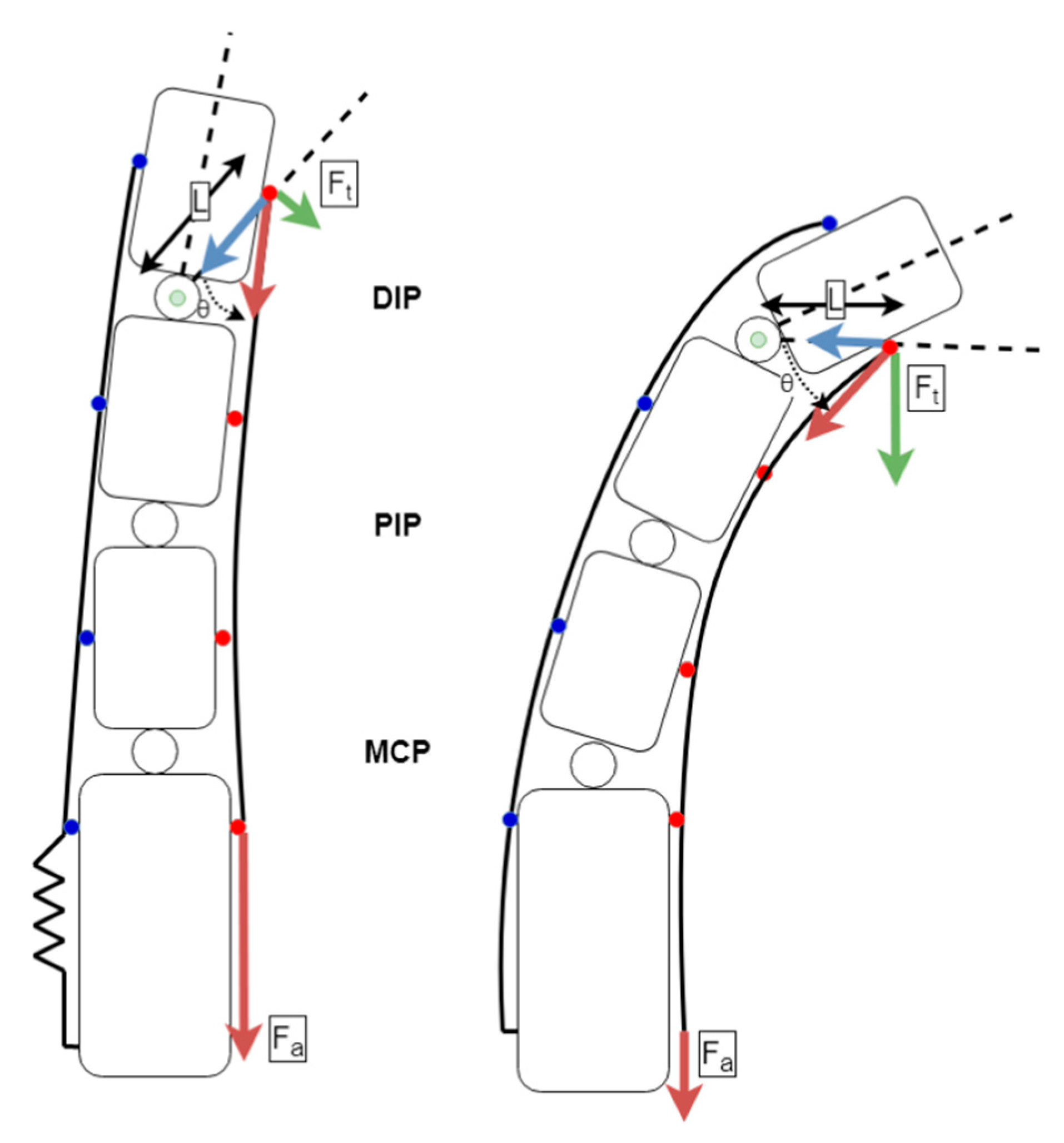
The design presented here utilizes a jointless structure that relies on the natural movement and joint constraints imposed by the patient’s skeleton. This actuation method is not suitable for injuries or ailments that have compromised the skeletal structure of the fingers. Our design also does not allow for controlling the rotation of the thumb’s carpometacarpal joint. This is achieved typically in other designs with hard linkages, which is not appropriate for soft-robotic designs such as ours. Our design allows for gras** motions, kee** the carpometacarpal joint in a natural range of motion for such tasks. The removal of the mechanical and structural linkages greatly simplifies the mechanical design and assembly process. Actuation was achieved by tensioning artificial tendons connected to the fingertips on the palmar side of the hand, as seen in
Figure 1. Elastic artificial tendons on the dorsal side of the hand were used to provide the opposing force needed for abduction. The elastic and inelastic tendons were designed to mimic the correct functioning of the human hand in gras** motions. Each finger was actuated using one custom-designed actuator mechanism.
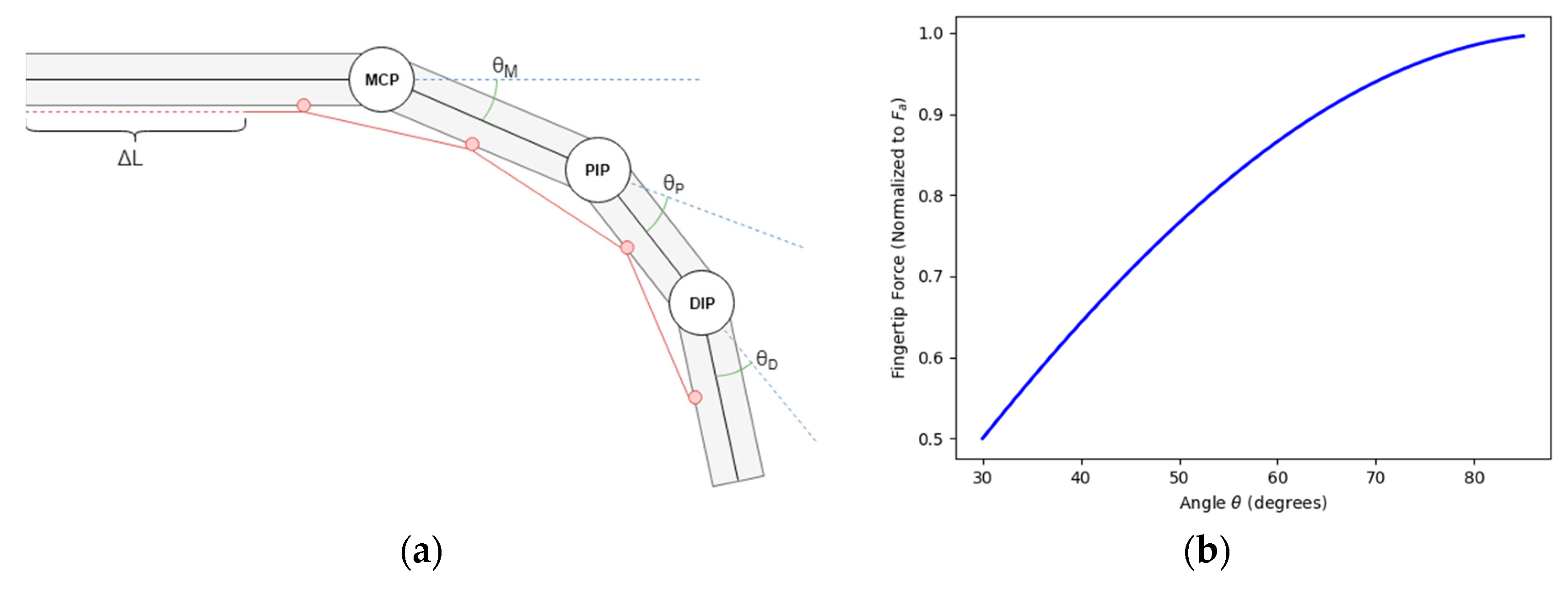
To achieve natural motion of a finger, the kinematic design borrowed heavily from the anatomy of a healthy human hand. The actuation force was provided by a tendon running down the palmar side of the fingers. The bone structure and musculature naturally constrain joint angles θ
M, θ
P and θ
D to a range of approximately 0–90 degrees. These joints are further constrained to a single plane of motion. The underactuated design relies on controlling the parameter ΔL, which translates to the length of the palmar tendon. As discussed later in the paper, ΔL is adjusted to allow for full extension of the finger at its greatest value (θ
M, θ
P and θ
D all equal to 0). When sufficient force is applied to the tendon θ
M, θ
P and θ
D begin to move and ΔL becomes smaller, moving the tendon attachment points (shown in red in
Figure 2a) closer to each other. The finger is considered fully actuated once θ
M, θ
P and θ
D have hit their natural joint constraints. The drawback of an underactuated design is that θ
M, θ
P and θ
D are not directly controllable. This, however, does not pose a significant issue due to the fact that the system is designed to mimic the operation of a healthy human hand.
The focus of this design was to impart a force normal to the fingertip that was consistent with that of a healthy human hand. The mathematical model was derived to help calculate the actuator torques needed to achieve this force. As shown in
Figure 1;
Figure 2b, the force normal to the finger changes with the angle of the distal phalanges. Thus, our determination of proper actuator torque was taken when the finger was at full extension, the worst-case scenario.
Figure 2b shows the relationship of the angle between the attachment point of the palmar tendon and the center of rotation of the DIP joint, both measurements obtained empirically from dimensions taken from the test subjects and the force. As the actuator force is applied to the palmar tendon and the finger is flexed, the torque applied to the DIP joint and in turn the force applied tangential to the radius of the circle centered on the DIP joint that contains the anchor point for the tendon increases. Thus, our determination of proper actuator torque was taken when the finger was at full extension, i.e., the worst-case scenario.
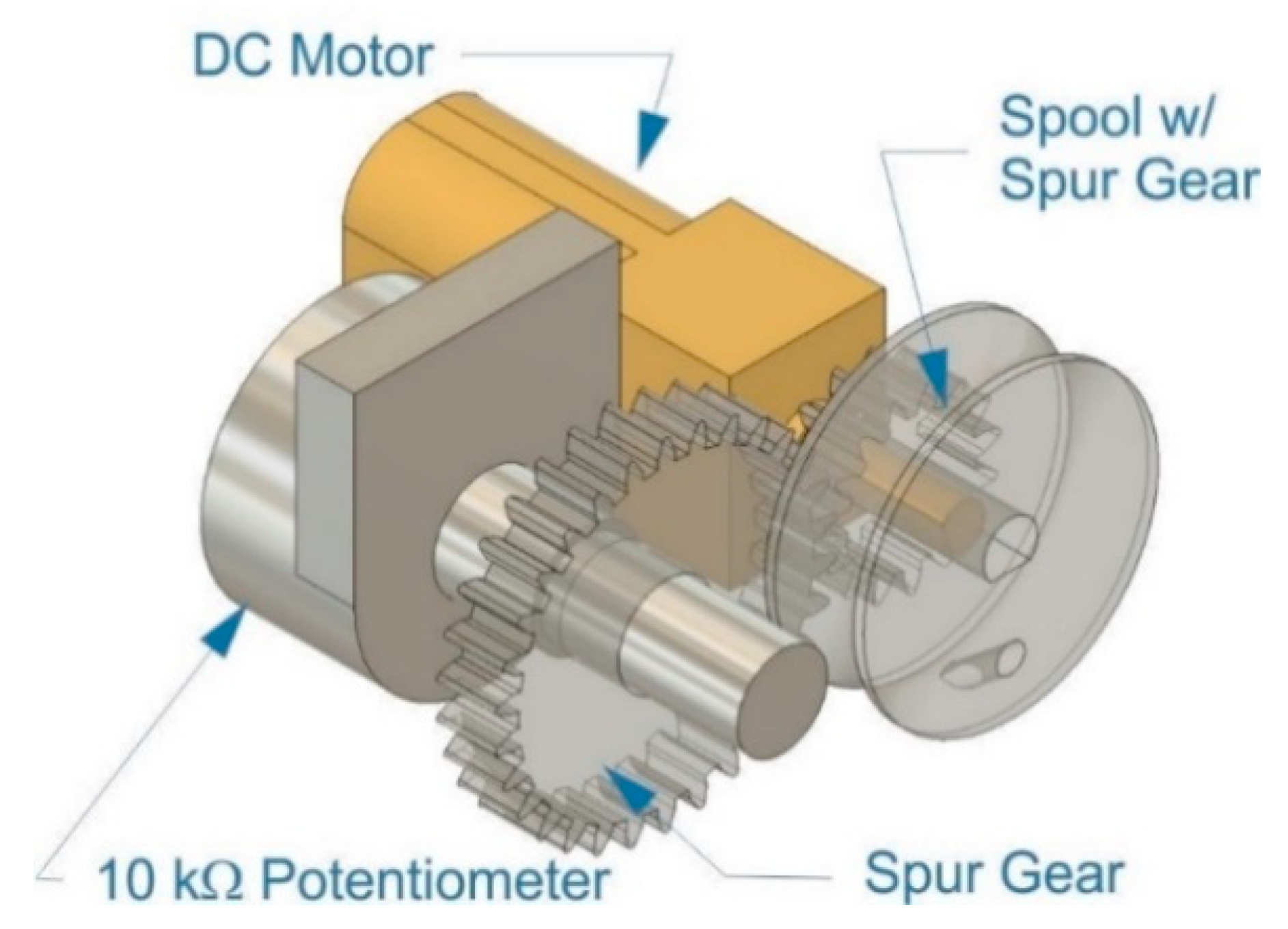
A linear actuation stroke, shown as ΔL in
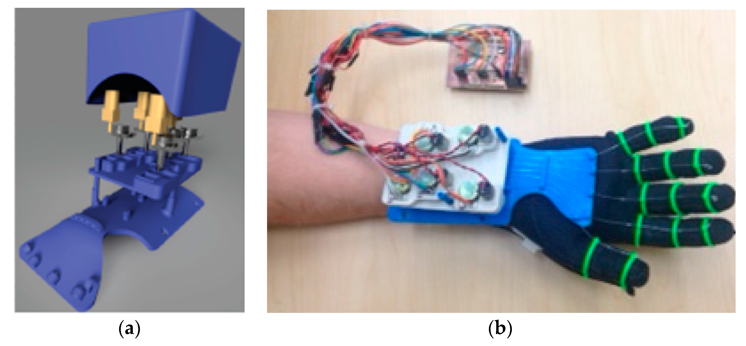
Figure 2a, was achieved by using the rotational motion of the DC motor to wind the palmar tendon around a spool. Position feedback was implemented by coupling a rotary potentiometer to the shaft of the DC motor using spur gears with a 2:1 potentiometer-to-motor shaft gear ratio in order to increase the tracking resolution of the potentiometer, as shown in
Figure 3. The brushed DC gearmotors are 6 V high-power carbon brush (HPCB) micro metal motors with a gear ratio of 298:1, weighing 9.5 g each, with dimensions of 10 × 12 × 26 mm and 3 mm shaft diameter, stall torque of 0.034 kg*m at 1.5 A stall current and output power of 0.65 W at maximum efficiency. The motors were driven by dual TB6612FNG motor drivers, which can control two motors each at constant current of 1.2 A (3.2 A peak). The potentiometers are 10 kΩ linear taper. The spur gear, the spool with the spur gear, the housing and enclosure for the custom actuator mechanism were 3D-printed. These custom actuators achieved the mechanical requirements needed for anthropomorphic actuation as well as being low-cost, non-proprietary and easy to assemble.
2.2. Mechanical Design
The mechanical design of the glove was based on the resting position of the hand, having the motor system actuate the closing of the hand and a passive system to return the hand to the resting position. This qualification made it necessary to have an inelastic material on the underside of the hand coupled to a motor system with position monitoring to close the hand and an elastic material on top of the hand that will return the hand to the neutral position. The elastic and inelastic tendons were secured to the fingers using 3D-printed rings. The motor system and position feedback system were mounted to the bottom side of the arm on a 3D-printed, ergonomically formed support system. The passive retraction system was mounted to the topside of the hand. All the separate components were secured to a 2.5 mm neoprene glove using a cyanoacrylate adhesive to form a contiguous unit.
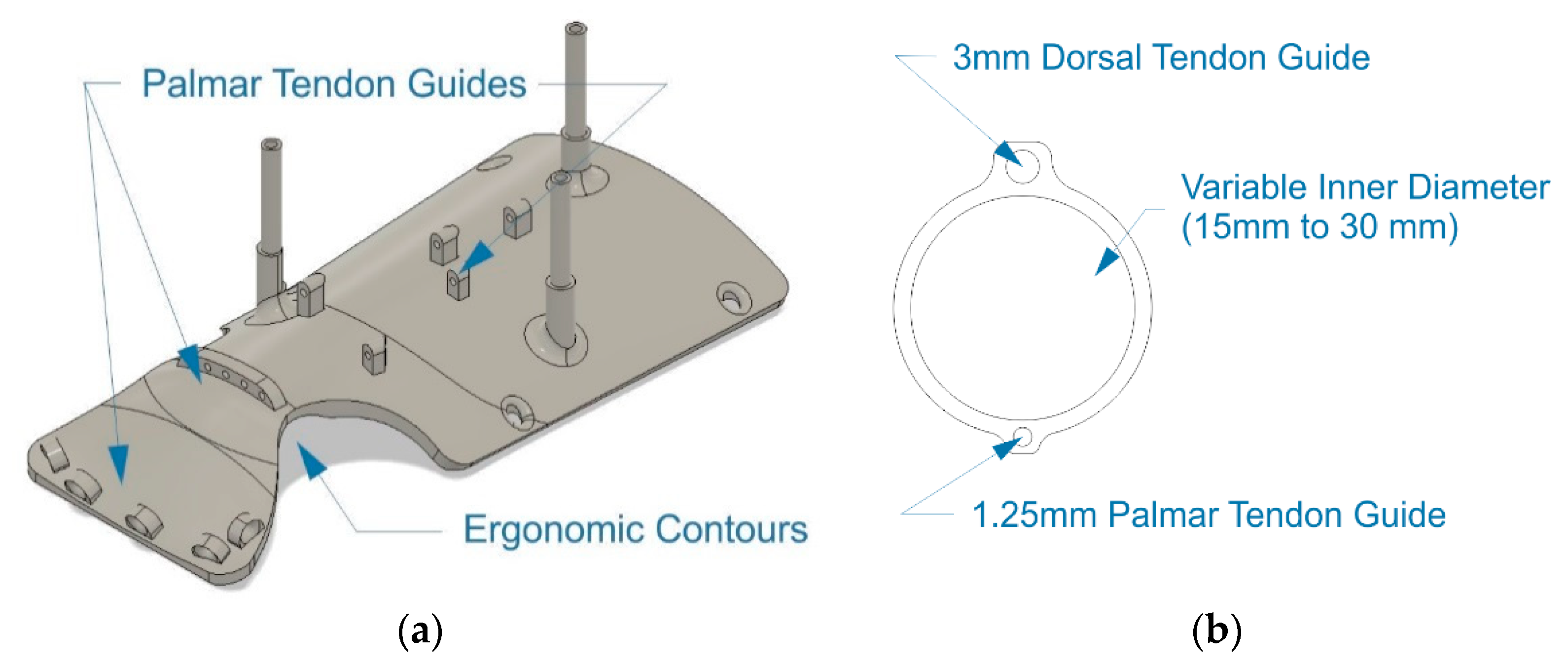
A set of low-profile rings was designed to affix the artificial tendons to the fingers, as shown in
Figure 4b. Sizes ranging from 15 to 35 mm in diameter were created with customization in mind, as the end user can choose sizes to fit their hand without any need to edit the 3D models. A support platform with ergonomic contouring was created to house the motor system, guide the palmar tendons from the actuation system to the fingers and keep the wrist straight, as seen in
Figure 4a.
The requirement of having a simple mechanical design was the most significant driver our mechanical design process, as the exoskeleton must be simple enough to be put together by any layperson. Our design incorporates a snap-fit structure consisting of the ergonomic wrist structure, motor driver holders and an enclosure; as shown in the blown-up mechanical model in
Figure 5a. The components were designed for simplicity, to be 3D-printed on any available 3D printer by the end-user and put together without any extra hardware or tools.
Furthermore, adaptability to a wide array of hand and finger sizes played a crucial role in the design process. The mechanics of the exoskeleton were designed in a modular fashion, with three sizes of the support platform, shown in
Figure 4a and 20 sizes of rings, shown in
Figure 4b, ranging from 15 to 35 mm to allow fitment for a wide range of hand and finger sizes. The artificial tendons providing the actuating and restoring force to the fingers are easily adapted to the user’s kinematics. The finger stroke length, seen as ΔL in
Figure 2a, can be customized by simply trimming the monofilament line to the correct length prior to securing it to the rings with the fingers fully extended. Once secured, the software then runs a calibration procedure to measure the appropriate ΔL for the user. The restorative force, provided by 1/8”shock-cord, can be customized in a similar manner.
Figure 5b shows the fully assembled robotic hand exoskeleton connected via a wire harness to the microcontroller. The top enclosure was purposefully removed in this figure to show the simplicity of construction and wire routing. The entire electromechanical assembly fits neatly within our mechanical enclosure, which is flat on top allowing two separate modes of operation while the hand is resting on a flat surface: one with the palm facing upwards and the other with the palm facing down with the flat surface of our enclosure resting on a table-top allowing for full range of motion of the fingers during a physical therapy session.
2.3. Control System
The Arduino Mega microcontroller was chosen as the main platform for all control, communication and signal processing as with 15 pulse-width modulation (PWM)-capable pins, it fulfills the requirements for the number of PWM pins needed to drive the DC motors, as well as an ample number of analog inputs (16) used for position monitoring. The Arduino primarily fulfills our requirement of being widely available at low cost. It also benefits from a large community of users and developers and access to code libraries available for a variety of interfacing options.
2.3.1. Electrical Design
A custom Arduino shield was designed to provide an interface to connect the Arduino to the various hardware components in the actuation mechanism. Arduino shields have become popular in the consumer market as they provide a simple plug-and-play interface between the microcontroller and the external system by integrating all necessary electronics and connectivity on a single printed-circuit board (PCB) that mirrors the Arduino form factor. Our Arduino shield featured three integrated TB6612 motor drivers with appropriate connectivity to facilitate the motor velocity and direction control. Additional headers provided an interface for the appropriate connections to be made between the potentiometers and the analog-to-digital converter (ADC), 5 V and ground pins on the Arduino. Three tactile pushbuttons were integrated into the shield to provide a rudimentary user interface for the calibration process and controls to manually operate the actuators, if needed.
Our custom shield could be manufactured by the end user using a PCB or CNC milling machine, or custom ordered (fully or partially assembled) from PCB fabrication and assembly houses for a very low price (estimates fit well within our required budget). While the form factor of a manufactured shield is preferred in the final constructions process, we have designed the mechanical enclosure with ample space to allow users to manually assemble the electrical components consisting of only wiring and motor drivers.
A 7.4V, 2200 mAh lithium polymer (LiPO) battery was chosen to power the system as LiPO batteries have the most stable discharge characteristics providing a steady current supply. The average current draw of one DC motor was measured to be approximately 350 mA while under load. Battery run time was calculated using the following equation.
The estimated run time accounts for a worst-case scenario where all the motors are constantly under load, which is rarely the case. A typical estimated load time per motor is in the order of ten times less than our worst-case scenario estimate. The runtime satisfies a typical physical therapy session of one hour with ample capacity to account for degradation of battery life, ensuring that the exoskeleton is operational well within the typical LiPo battery 500 discharge cycles lifetime and accounting for typical degradation of LiPo performance by 25% after the first 200 recharge cycles.
2.3.2. Joint Position Control
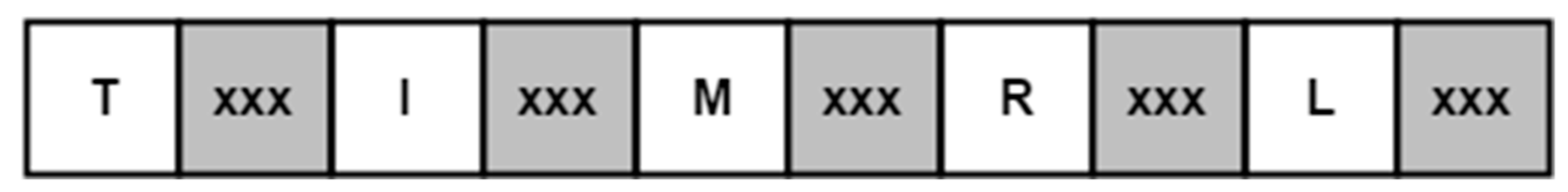
The hardware control system was designed to accept input from a number of various sources through the use of a structured data packet, as seen in
Figure 6, formatted to encode the desired position of each finger, expressed as a value ranging from 0 to 100 percent of the user-calibrated actuation range. The hardware control input was designed to be ambivalent of the rest of the system, allowing data to be sent from a controlling device or read from a file encoding a predetermined exercise or therapy routine. Once received, the data packet is then deconstructed by a parsing function that recognizes the alphanumeric characters and parses the proceeding integer value (represented by ‘xxx’ in
Figure 6), storing it in the appropriate variable. For example, when the parser reads the ‘M’ character in the packet, it will store the number read after the ‘M’ in the variable corresponding to the goal position of the middle finger. The parser continues to run until the serial buffer no longer has data queued.
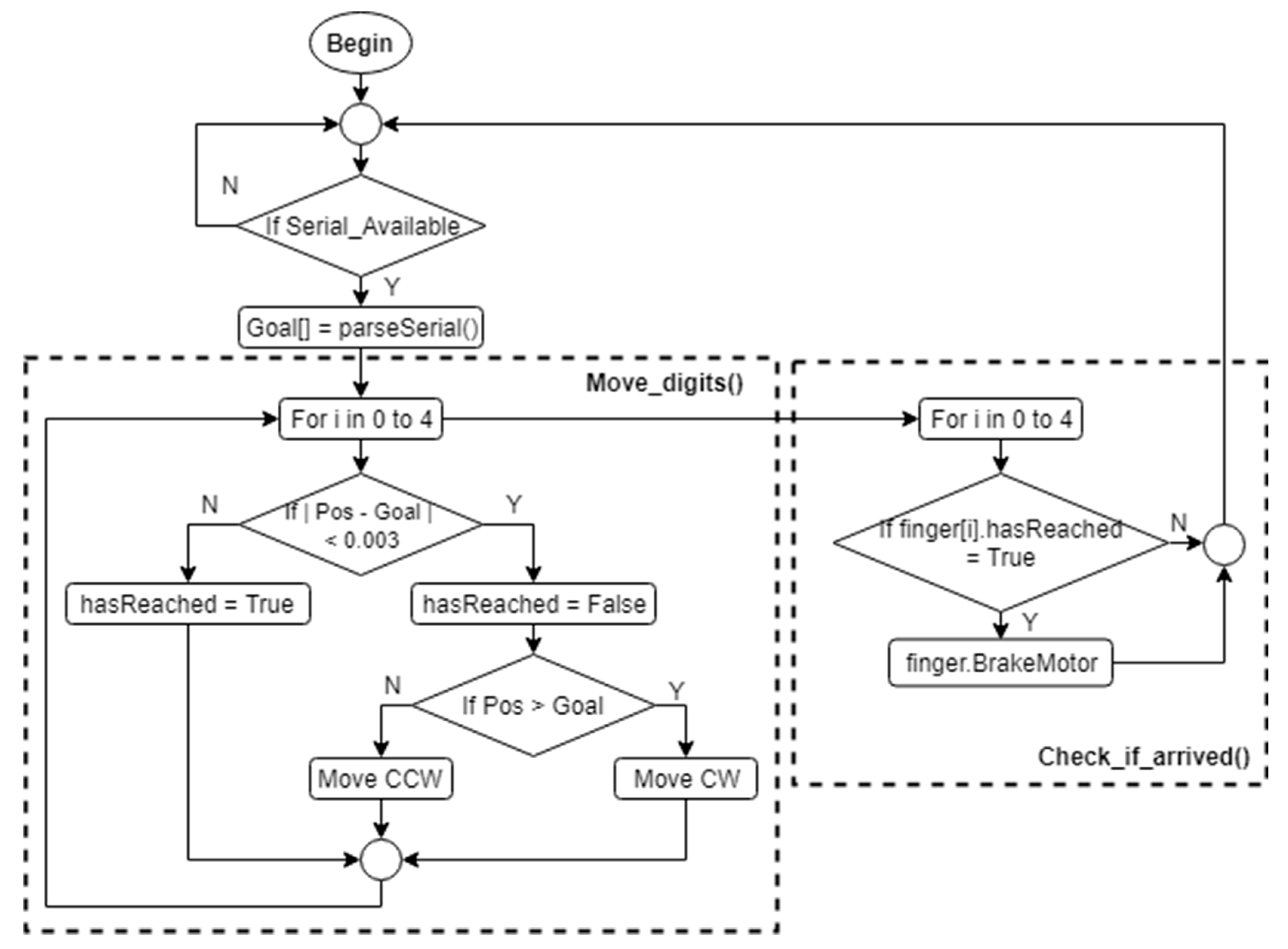
The stroke length ΔL, discussed in
Section 2.1, for each finger is controlled using a closed-loop proportional derivative (PD) algorithm running at 50 Hz, shown in
Figure 7. The set point of the controller was obtained by map** the percentage read from the control data packet to the corresponding value within the user’s calibrated actuation range. The algorithm first checks if a data packet is available in the serial buffer and, if so, then it parses the packet, as discussed previously. For each digit, the algorithm then checks the desired position and, if the digit needs to be moved, proceeds with driving the corresponding motor either clock-wise (CW) or counter-clock-wise (CCW) until the desired position has been reached, at which time it would engage motor braking.
A motor status check routine was implemented to stop the motors and apply a braking force once the error in the PD controller was reduced to a value sufficiently close to zero, as shown in
Figure 8. The proportional and derivative components of the positional error are evaluated against the desired position at 50Hz and the motor speed is adjusted accordingly.
3. Results
Tests of the soft robotic exoskeleton were conducted to verify that the range of motion of the digits and the forces exerted at the fingertip coincide with those of a healthy human hand. The tests were conducted by first establishing a baseline for a healthy individual’s natural range of motion shown in blue in the
Figure 9,
Figure 10 and
Figure 11 below and using the square symbol in the
Figure 12 block and whiskers plot. The data was gathered from a Qualisys Miqus camera setup used for visual metrology and motion capture. The system consists of four high-resolution, high frame rate cameras and an array of visual markers placed on the DIP, PIP and MCP joints. Our experimental setup provides tracking information in real time at latencies close to 3 ms. Each test was performed for a duration of one second each, where each finger would first curl and then uncurl. The duration of the test was selected to show the time needed to fully flex and relax each digit. The range of motion from the baseline data was then used as a control signal for the actuation of the soft robotic hand exoskeleton.
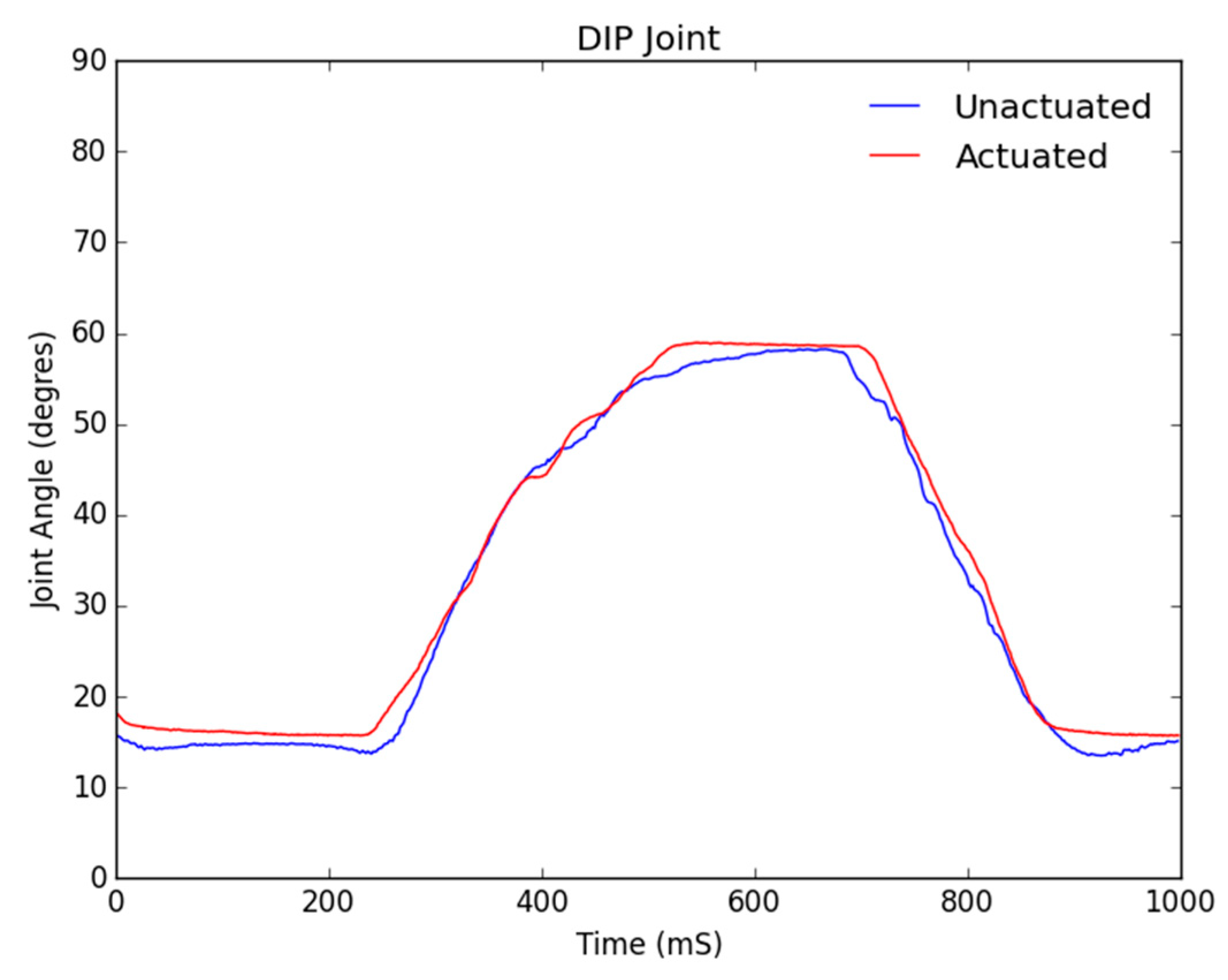
The three figures below show the joint angles observed in the distal interphalangeal (DIP), proximal interphalangeal (PIP) and metacarpophalangeal (MCP) joints of a typical baseline healthy individual’s index finger range of motion. As the controls of each digit and subsequent motor are fundamentally the same within our control algorithm, the following test results extend to all digits of the soft robotic hand exoskeleton, except for the thumb which only has a DIP and an MCP joint.
From
Figure 9;
Figure 10, it can be seen that the DIP and PIP joints track very closely to the control with a negligible relative error as compared to natural range of motion. This result is expected as our soft robotic exoskeleton is tendon-driven and the force exerted on the tendon, which is anchored at the top of the DIP joint, will move the DIP joint first, which is why the actuated DIP data follows the unactuated data immediately and closely.
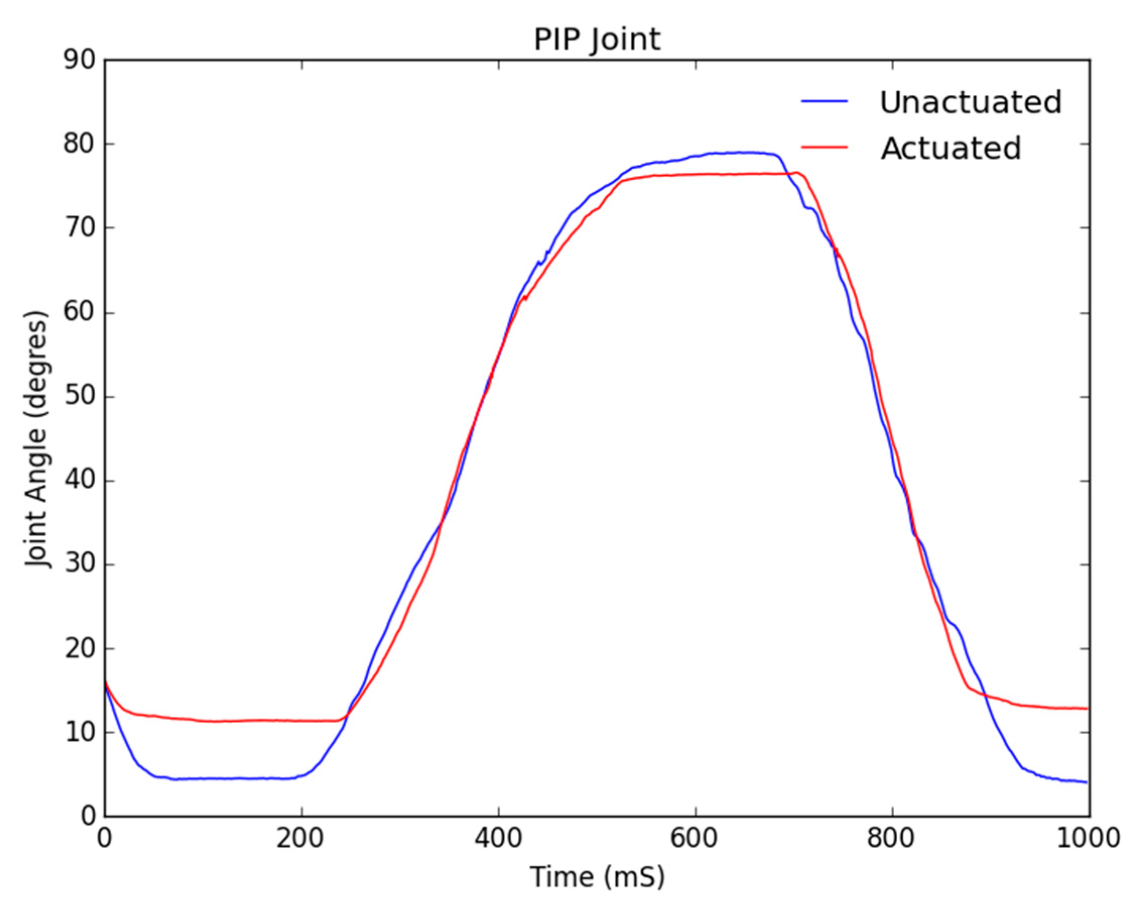
Figure 10 shows the tracking of the PIP joint and consequently from our previous argument, it was expected and observed that the while the tracking between the unactuated and actuated data is close, it follows with an initial delay of about 200 ms, while the movement of the DIP triggers movement in the PIP.
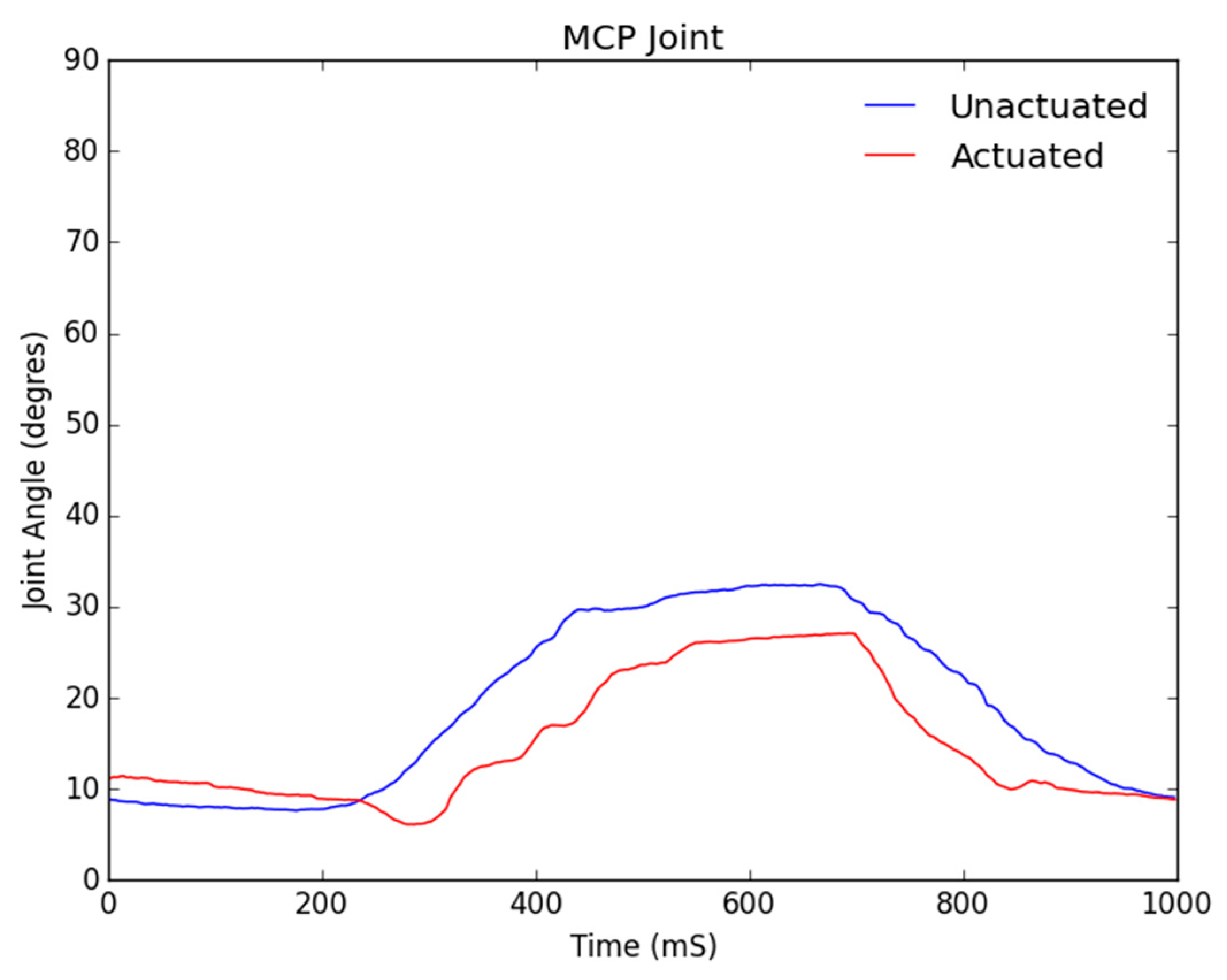
Figure 11 shows the motion analysis data for the MCP joint, where the blue line represents the baseline range of motion of a healthy individual’s hand and the red line shows the joint angle for the motor-manipulated finger and resulting joint angle in degrees for its MCP portion. As can be seen from the figure, the MCP joint did not track the control signal as closely as the PIP and DIP did. The error in tracking was at a maximum of six degrees and this again is a result of the soft tendon actuation affecting the MCP joint last.
In addition to verifying the kinematic functionality of the design, the force exerted by the fingertips was measured for both an unactuated and fully actuated hand in order to determine if the design could be useful in hel** patients to complete daily tasks. This data was collected using a test setup designed to keep the wrist and finger straight as the motors were actuated. A standard load cell was placed horizontally, while each fingertip of the hand was placed on top of it with the hand was fully extended. The force was then measured using the load cell placed parallel to the fingertip, measuring the normal force. As the test was conducted with the fingers in the fully extended position, these results correspond to the minimum force that our exoskeleton can exert because, due to the force vector, the maximum force is experienced at the fully flexed position.
HyunKi In et al. [
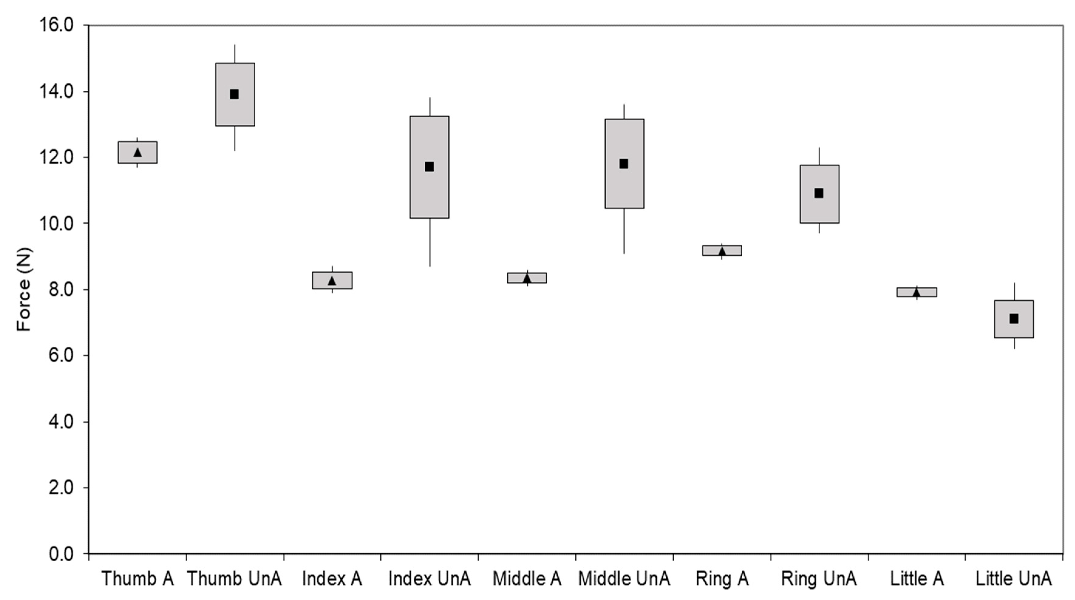
34] found that most daily activities, such as pulling up a zipper or picking up a glass, require less than 10.5 N of force. The results presented in
Figure 12 show that the force exerted by the mechanically actuated hand is approximately 9 N, which is within the desired range for most daily activities.
Figure 12 also shows that while the unactuated measurements are slightly higher than their actuated counterparts, they may vary significantly, mostly within a couple of Newtons, between test subjects. The actuated forces are tightly grouped with low standard deviation and high precision, representing the desired effect of repeatability and stability in motion. In addition, based on the durability cycle of the integrated battery we have tested the run-time and durability of the soft robotic hand exoskeleton to perform without any observable electrical or mechanical degradation for at least 500 cycles, meeting our design’s requirements of run-time and mechanical performance.
4. Discussion
The results verify that the range of motion of the digits and the forces exerted at the fingertips coincide with those of a healthy human hand. While it cannot be expected for a soft-robotic hand exoskeleton driven by external anchored soft tendons to exactly mimic a healthy individual’s natural range of motion, the results show that our design can do so successfully with a low relative error. The satisfactory results, coupled with the fact that our soft robotic hand exoskeleton is built entirely out of commercial-off-the-shelf components on a budget of less than $200 make our design unique and accessible in an ecosystem of proprietary, close-sourced, bulky and unaffordable options.
Compared to the two previously mentioned non-customizable commercially available systems, The Hand of Hope [
17,
30] and Festo Exohand [
31], our design provides an improvement in several respects. Both of these designs use serial link manipulators to actuate fingers, while our design uses compliant soft tendon-driven actuation, while improving on the limited range of motion in the metacarpophalangeal (MCP) and proximal interphalangeal (PIP) joints. Although our design is like the Festo Exo-Hand [
31] in respect to user-specific dimensioning through the use of 3D scanners and a laser sintering process, the improvement is in our design’s portability and total weight. When compared to the soft robotic glove of Polygerinos et al. [
32], although our designs are similar in the robotic exoskeleton design’s pliability, their fabrication method using custom designed, naturally compliant soft-actuators and custom-molded, hydraulically controlled actuators created from a soft silicone rubber compound reinforced with mesh is much more complicated and arduously replicable by lay end-users. Their systems also require attachment to a hydraulic pump weighing over 3 kg for untethered use, while our system is portable and untethered by design weighing less than 400 g, including the weight of the battery, which is 132 g alone.
What makes our soft robotic exoskeleton truly unique from the competition are not only its low cost, portability and accessibility, but also the therapy modality. Our platform benefits from our web-based patient-doctor interface, as shown in
Figure 13. Much of the research that has been done on rehabilitation robotics has focused solely on the accuracy of the kinematics and dynamics of the mechanical system. This volume of research and development has produced a myriad of solutions that often remain inaccessible to patients not only due to their cost and/or weight but, most importantly, because they were simply not built to be standalone take-home solutions, meant to be used with minimal guidance from physicians. The key to a successful therapy regimen is consistency, a requirement often met with difficulty by patients in remote areas, with limited mobility and access to modern medical services. By making an accessible device that can be consistently used by patients with minimal supervision from therapists, we would only tackle half of the problem. We believe that a readily available communication channel between patients and their physicians is equally important to the successful implementation of robotic therapy regimens.
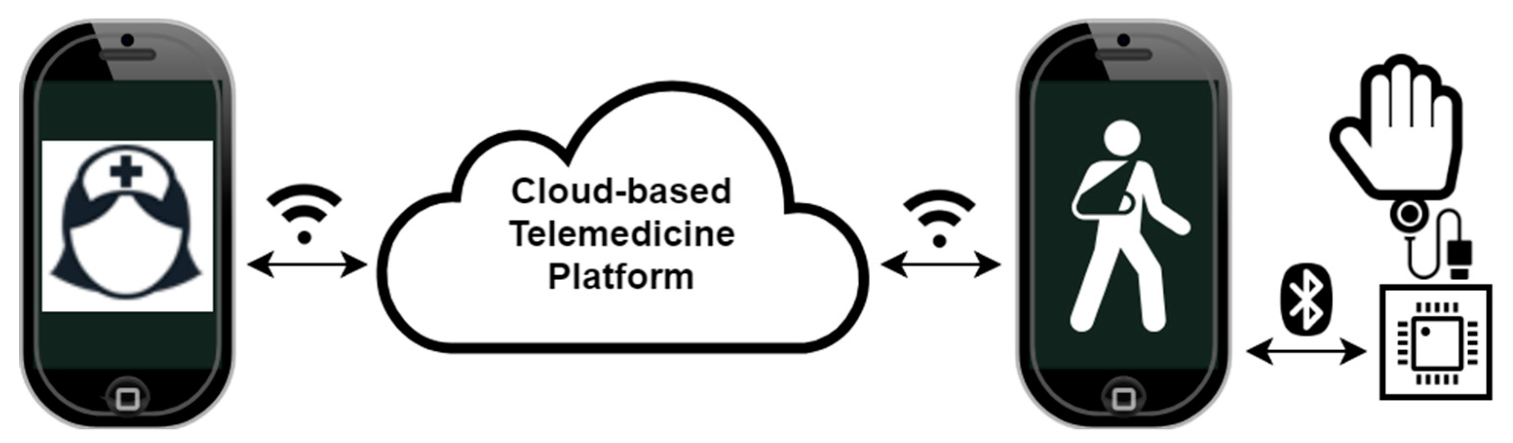
The cloud-based telemedicine platform, illustrated in
Figure 13, consists of smartphone applications for therapists and patients enabling first and foremost direct communication between the users as well as remote control of the medical device. The platform enables real-time control of the medical device by the practitioner, effectively enabling them to prescribe and execute a live therapy session for the patient. Alternatively, the prescribed regimen could be executed remotely by the patient at their own convenience later. The platform may store personal device calibrations and diagnostic data so that the therapists can be assured that the medical device is fit to perform the duty of remotely assisted physical therapy. The platform also takes advantage of the large dataset available from the many deployed devices and their generated usage statistics to detect and predict public health trends. Most importantly, after a few initial calibrations and remotely assisted therapy sessions, the therapists can be assured that the patient who is prescribed a long-term therapy regimen can safely execute it in an automated manner while providing therapy tracking and analysis feedback to both the patient and therapist.
The platform is envisioned to provide service to a variety of embedded application-specific medical devices, such as our soft robotic hand exoskeleton. The requirement is that the devices are controllable via smartphone and/or auxiliary wireless sensor networks. The smartphone app functionality is to load/save usage data, therapy regimens and personalized device calibrations from the cloud. Real-time streaming of therapy data to the cloud for direct physician monitoring are enabled by integrating the app with the cloud platform, as described previously. To maximize the impact of our platform, the medical devices must be simple, low-cost and constructible and/or serviceable by patients.


