1. Introduction
Minimum quantity lubrication (MQL) with less use of lubricating oils [
1] and dry lubrication with positive use of solid lubricating mechanisms [
2] have been highlighted to reduce the environmental burdens in practical operations toward green metal forming [
3]. In particular, solid lubrication is indispensable in dry metal forming and dry machining to reduce tool wear and to qualify product surfaces [
4]. The use of solid lubricants such as graphite and MoS
2 (Molybdenum die-sulfide) provides a way to form the slip** buffer layer between the die and work [
5]. As depicted in
Figure 1a, powders and coatings have been utilized as a lubricating buffer layer in practice. Self-lubricating coating provides a means to prevent the protective coating from oxidation wear and severe galling as depicted in
Figure 1b [
6,
7,
8]. When using the ta-DLC or tetragonal amorphous carbon coating, the in situ synthesized polymer layer is wrought as a layer for boundary lubrication [
6]. In particular, the fluorine- and chlorine-bearing titanium nitride coating is wrought to reduce the friction and specific wear volume in dry forming [
7]. These two categorized methods have been effective in most dry metal forming. However, severe galling wears cannot be avoided when using these approaches alone, especially when working with titanium and titanium alloys [
8,
9,
10].
Most DLC coatings and binary/ternary nitride coatings are subjected to the adhesion of fresh titanium fragments, even in BOD (ball-on-disc) testing [
8,
9]. TiN, TiCN and TiAlN coatings experience high friction transients before seizure to titanium balls [
8]. The textured substrate surface exhibits relatively low friction with μ = 0.2 under MoS
2 lubrication [
9]. Irrespective of die material selection for deep drawing pure titanium sheets, the drawing ratio was limited to be far less than 2.0 [
10]. In every forging step, titanium oxide debris particles can splash in the air and be deposited onto the die surface in practical operation [
11]. In the free-forging and near-net forging process in hot conditions [
12], galling easily occurs in every step of the hot forging processes.
Figure 2 depicts a new solid lubrication method with the use of in situ formed interstitial solute film on the contact interface. As depicted in
Figure 2a, the solute atoms or clusters are embedded into the die substrate. Under the stress gradient across the contact interface between the die and metallic work, these solutes isolate from the die matrix, diffuse to the interface through the nanocluster boundary network in
Figure 2b, and agglomerate by themselves to form a tribofilm on the interface in
Figure 2c. In the literature, carbon has been employed as the interstitial solute (S). After [
13], free carbon supersaturated AISI316 stainless steels with an extremely high content of 12 at% were achieved through gas-phase carburizing at 743 K. The carbon supersaturated (CS) steels can be prepared by surface treatment to drive the supersaturation process. In particular, free carbon supersaturated and clustered in steels as reported in [
14]. Free carbon isolated from the CS state during steel processing as stated in [
15]. These findings in the literature suggest that the in situ solid lubrication model in
Figure 2 can be applied to steel dies by develo** an adequate carbon supersaturation process.
In previous studies, low temperature plasma carburizing was utilized to facilitate carbon supersaturation into steel die substrates [
16]. SKD11 and AISI420J2 dies were carburized at low holding temperatures to prepare the carbon supersaturated dies (CS dies) for cold upsetting of pure titanium works, respectively. As reported in [
11,
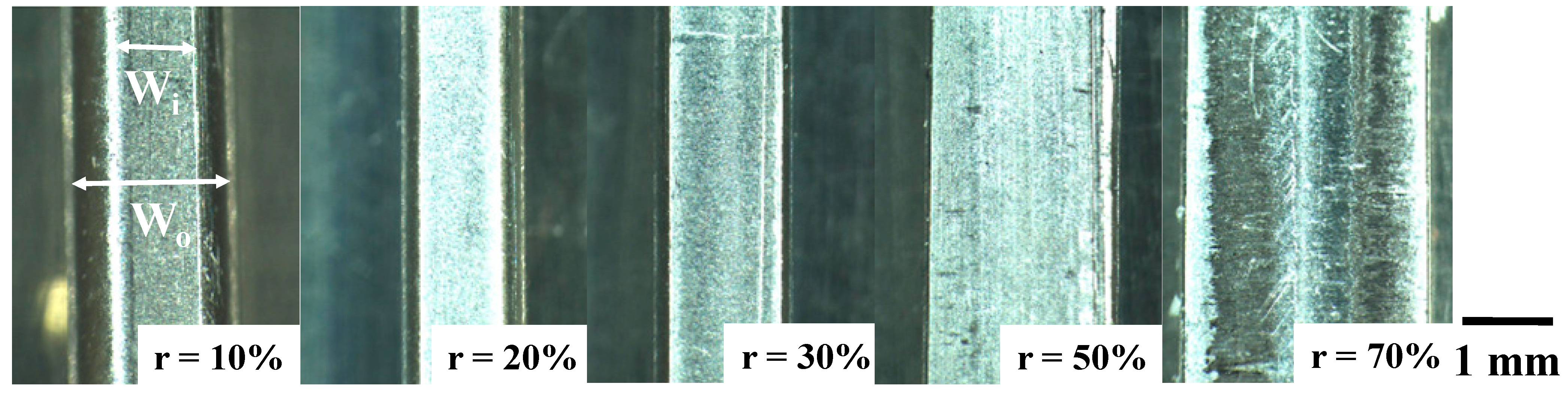
17], the reduction in thickness was limited by 20% by using the bare tool and stainless steel dies due to the risk of galling on the interface in normal forging operations. When using the CS-SKD11 and CS-AISI420J2 punches and dies, no adhesion of fresh titanium flakes and no deposition of titanium oxide debris were seen after forging even with a reduction in thickness of 70%.
In addition, the hot CVD (chemical vapor deposition) process was utilized to facilitate carbon supersaturation into the SiC die substrates by controlling the flow rate ratio of methane into source gas for the chemical deposition of β-SiC coating [
18]. The thick CS-βSiC layer was coated onto the SiC die substrate with a thickness greater than 4 mm. Even in cold upsetting of pure titanium works, they were uniformly forged under a reduction in thickness of 70% without any adhesion of titanium flakes or debris particles. The 3C-structured β-SiC coating layer with its sufficiently high thickness was directly utilized as a die material for the forging process of titanium and titanium alloy works. This CS-βSiC die has high enough heat resistance to be used for hot and warm forging processes at elevated temperatures higher than 1000 K.
In the present paper, the in situ tribofilm formation model for solid lubrication is stated with reference to previous studies on the activity of interstitial solutes in steels even under the stress gradient. Two types of carbon supersaturation process are introduced to prepare the CS-SKD11 dies and CS-βSiC-coated SiC dies for experimental demonstration on the in situ solid lubrication model. The low temperature plasma carburizing system is utilized to achieve carbon supersaturation in SKD11 discs, punches, and dies, respectively. A thermal CVD system is also utilized to achieve carbon supersaturation in βSiC with its co-deposition onto the SiC dies by controlling the carbon source. The upsetting processes are performed to prove that the low friction and low galling-wear conditions are preserved by using CS tools. SEM (scanning electron microscopy)-EDX (energy dispersive X-ray spectroscopy) and Raman spectroscopic analyses are employed to describe the free-carbon tribofilm formation on the contact interface. The in situ solid model on the carbon solute isolation, diffusion and agglomeration is discussed through the precise nanostructure analysis of the CS tools based on the equivalence between the nitrogen and carbon supersaturation processes.
2. Materials and Methods
2.1. Two Carbon Supersaturation Processes
Two types of carbon supersaturation process were utilized to prepare the CS-metallic tools and the CS-ceramic tools for experimental demonstration on the in situ solid lubrication model. The low temperature plasma carburizing system (YS-Electric Industry, Co., Ltd.; Kofu, Japan) was used for carbon supersaturation into the heat-treated SKD11 disc and die substrates under the processing conditions in
Table 1.
As schematically depicted in
Figure 3a, a hollow cathode setup was utilized to intensify the population of CH radicals and carbon ions. A thermocouple was embedded into this hollow unit in the vicinity of the substrates. In the following plasma carburizing process, the specimen was placed into the hollow cathode setup before evacuation down to the base pressure of 0.01 Pa. Argon gas was introduced at the specified pressure for heating up to 673 K. After presputtering for 1.8 ks, the specimen was carburized at 673 K for 14.4 ks. The overview of this carburizing system is depicted in
Figure 4a. The matching between input and output powers was automatically adjusted by the frequency control around 2 MHz in an RF-power generator.
Thick SiC coatings were highlighted in the literature [
19,
20]. Among them, a thermal CVD system (Shinko-Seiki, Co., Ltd.; Kobe, Japan) was used to achieve carbon supersaturation to the co-deposited βSiC coating onto the SiC die substrate by controlling the carbon source gas flow rate. As illustrated in
Figure 3b, a sintered SiC block with an average porosity of 0.5% was prepared as a substrate to make a thick SiC coating via the thermal CVD process at 1500 K for 108 ks. Silicon chloride and methane gases were selected as the silicon and carbon sources, respectively. They were mixed with hydrogen gas and introduced using a flow rate of 500 mL/min to the thermal reactor in the present CVD system. The thickness of the βSiC coating was 4 mm. After cooling down in an inert gas atmosphere, the βSiC-coated SiC block was directly cut using a diamond saw and polished using chemical buffing to shape the SiC-coated SiC punch and die. An overview of thermal CVD system is depicted in
Figure 4b.
2.2. Work Materials
Pure titanium wires and plates were respectively utilized for the upsetting experiments. The chemical composition of pure titanium materials consists of hydrogen by 0.0012 mass%, oxygen by 0.097 mass%, nitrogen by 0.007 mass%, iron by 0.042 mass%, carbon by 0.007 mass%, and titanium for balance. The flow stress was 230 MPa, and the Young’s modulus was 110 GPa.
2.3. Upsetting Experiments
A CNC (computer numerical control)-stam** system (Hoden Seimitsu; Kanagawa, Japan) was employed for the upsetting experiments with the use of two different CS die pairs. The CS-SKD11 punch and die were fixed into the upper and lower cassette die sets, respectively, as depicted in
Figure 5a. Those two die sets were cemented to the upper and lower bolsters of the CNC-stam** system with stroke control capability. The stroke was controlled by moving down the upper bolster to the specified position for reduction in thickness in work materials. The loading speed was constant at 10 mm/s. In a similar manner, the CS-βSiC-coated SiC punch and die were setup in the CNC stamper, as shown in
Figure 5b. In both experiments, the load cell was embedded into the lower die set to monitor the variation in applied load by controlling the stroke.
2.4. Material and Mechanical Characterization
XRD (X-Ray Diffraction; D8, Bruker, Toyama, Japan) was used to detect the peak shift induced by carbon supersaturation. Optical microscopy (Shimazu, Co., Ltd., Kyoto, Japan) was first employed to understand the morphology of the contact interface on the punch. SEM-EDX (JOEL, Tokyo, Japan) was utilized for microstructure analysis on the contact interface. Raman spectroscopy (Nihon-Kogaku, Co., Ltd.; Tokyo, Japan) was utilized to analyze the binding state of iron, chromium, titanium, oxygen and carbon on the interface of the CS-SKD11 punch. It was also used to analyze the binding state of silicon, oxygen, titanium and carbon on the interface of the CS-βSiC-coated SiC punch.
4. Discussion
Low friction and low work hardening of titanium work without adhesive wear or galling is common in upsetting processes using CS-SKD11 dies and CS-βSiC-coated SiC dies. This is a result of the in situ formation of a free-carbon tribofilm on the contact interface between dies and titanium work.
Let us discuss the mechanism in
Figure 2 using EBSD (electron back-scattering diffraction) and STEM (scanning transmission electron microscopy) with reference to several studies in the literature. Theoretical study using the first-principles calculation demonstrated the equivalence between nitrogen supersaturation (NS) and carbon supersaturation (CS) processes involving irons [
29]. The α-iron supercell lattice expands itself through occupation of its octahedral vacancy site by supersaturated interstitial solute. The carbon or nitrogen solute attracts its surrounding iron atoms to modify the electric structure of iron. These are common to two supersaturation processes. This equivalence is also experimentally validated in [
30]. The peak shift of α-iron to lower 2θ by nitrogen and carbon supersaturation is observed by precise XRD analysis. The improvement of corrosion resistance by NS stainless steels is explained by the change in electric structure by solute supersaturation. Using these experimental results on the precise analyses on the NS stainless steels and tool steels, let us describe the role of interstitial-induced nanostructure to drive the isolation and diffusion of free-carbon atoms from the CS dies. Then, the effect of carbon interstitial supersaturation on microstructure evolution is explained by microstructure analysis of the nitrogen supersaturated dies.
EBSD and STEM were utilized to analyze crystallographic misorientation in the cross-section of NS die.
Figure 13a depicts the KAM (Kernel angle misorientation) profile at the NS layer toward the nitriding front end. The whole cross-section of the NS layer is covered by a higher angle misorientation than 5°. This implies that the NS die microstructure is subjected to high plastic straining everywhere. After [
31], the highly plastically strained microstructure is induced by slip-line field formation along the crystallographic orientation of (111).
Figure 13b shows the LAADF image of the NS layer by STEM; the skewed slip lines are densely observed in the image. This proves that interstitial supersaturation accompanies high plastic straining to modify the original microstructure to have a fine diffusion network of interstitial atoms. That is, the carbon solutes can diffuse themselves through the cluster boundary network.
As seen in
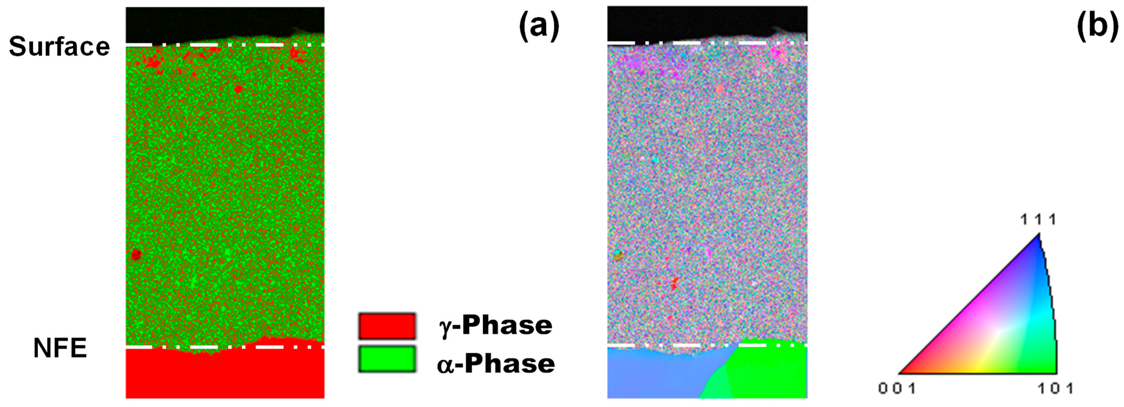
Figure 6a, α- and γ- broad peaks are detected by XRD as a shifted peak by NS and CS. NS and CS layers have fine clustering and a two-phase structure. EBSD is utilized to describe this two-phase nanostructure by using the phase map and inverse pole figure (IPF) map. As shown in
Figure 14, each nanograin with γ-phase is neighboring another nanograin with α-phase. This implies that each cluster in
Figure 13b corresponds to a nanograin in
Figure 14a,b. That is, NS and CS modify the original microstructure of the dies to a clustered nanostructure with different crystallographic structures. The cluster with rich interstitial solutes corresponds to the γ-phase nanograin, whereas the cluster with poor interstitial solutes corresponds to the α-phase nanograin [
32]. These two different nanograins are neighboring each other. Under the externally applied stress gradient, the interstitial solutes in clusters make a jum** diffusion from the original vacancy site to the other and further diffuse by themselves through the cluster boundary to the contact interface after [
33].
This mechanism is true to the carbon solute isolation and diffusion in the CS-SKD11 dies. Before metal forming, the supersaturated carbon solutes occupy each vacancy site both in the carbon-rich and carbon-poor clusters. The cluster boundary works as a stable zone for carbon solute to jump up from the original site in each cluster under the stress gradient field. Then, each carbon solute diffuses through the cluster boundaries to the hot spots on the contact interface and forms a free-carbon tribofilm in situ.
Let us consider the galling free forging of titanium by CS-βSiC from two aspects. First, the electric structure differs between covalent βSiC with a 3C structure and metallic titanium work. After the first-principles calculation in [
34], two matters with nearly the same density of state (DOS) in their local electron structure, are easy to adhere to each other; whereas, two with significant differences in DOS have less bound interface. Dense β-SiC coating punch and die have a covalent bonding state in the cubic structure, whereas titanium is a typical transition metal that exhibits metallic bonding characterized by free electron pairs. No detection of metallic titanium by the EDX analysis in
Figure 12 reveals that DOS on the βSiC surface still remains completely separate from that on the metallic titanium. Detection of titanium oxide on the βSiC die surface also proves that flakes of oxide layer on the work wire are mechanically splashed into the air and are deposited onto the slightly rough surface of the βSiC die surface.
Secondly, the free-carbon agglomerates appearing as a dot on the contact interface between βSiC and titanium work in
Figure 12 must be considered. XRD analysis reveals that lattice expansion by CS-βSiC is detected by the peak shift in the lower 2θ. Although each cell in βSiC elastically strains by itself, the neighboring cells distort with much less plastic strain. Most of the im**ed carbon solutes occupy the vacancy site near the zone boundary or the defective zones near the grain boundaries. Under the stress gradient, these free-carbon solutes isolate from those sites to zone and grain boundaries and diffuse through these paths to the hot spots on the contact interface in a similar manner to the in situ solid lubrication process observed in CS-SKD11 dies. In fact, the free-carbon agglomerate size in
Figure 12a is equivalent to the grain size.
5. Conclusions
Carbon supersaturated SKD11 dies and βSiC-coated SiC dies were prepared for dry, cold forging experiments. Pure titanium wires were upset in a single shot by a 70% reduction in thickness with low friction and low galling wear. The precise SEM-EDX and Raman spectroscopy analyses proved that an amorphous free-carbon tribofilm was formed in situ on the true contact interface between the CS dies and the titanium work. This low friction and low galling wear on the contact interface suppressed the work hardening in the titanium work. These features in the metal-forming tribology are favored for high quality manufacturing of titanium medical tools and parts.
EBSD and STEM analyses showed that the nanostructures of CS-SKD11 dies accommodate the diffusion network for carbon solutes. When the stress gradient is applied during metal forming, these solutes diffuse and agglomerate themselves as a tribofilm on the contact interface. This in situ solid lubrication by free-carbon dots characterizes the dry, cold upsetting behavior of the CS-βSiC coating die. The carbon solutes near the zone and grain boundaries isolate from βSiC grains, diffuse to the interface through these boundary networks and agglomerate as free-carbon dots with nearly the same size as βSiC grains.
Galling-free metal forming using CS tools is useful in forging, press-forging and in the fine blanking steps used to achieve near-net sha** of difficult-to-form work materials even with a severe plastic flow of works. The die material design is essential to control the constituent alloying elements with different affinities to the interstitial solutes in the supersaturation process and to facilitate the in situ formation of tribofilms on the hot spots of dies in a feasible way in each metal forming step.


