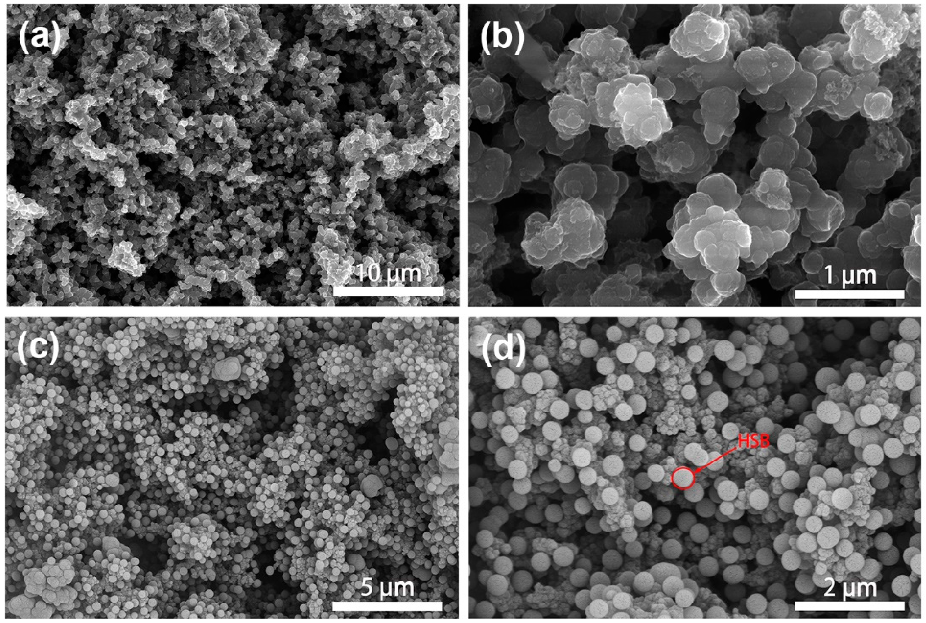
3.2. Morphology Analysis
Figure 4 shows the typical morphological structures of pure PPy and PPy/HSB-0.6 composite. As is in
Figure 4a, homogeneous PPy prepared by the redox method forms an irregular cauliflower structure with cluster sizes of about 500 nm. The cluster has a smooth surface, which provides conditions for uniform distribution of HSB. Pure HSB displays a morphology of spheres with a size about 500 nm, as shown in
Figure S2b. As to the PPy/HSB composites, HSB reacts in situ in the PPy pores as a polar molecule, forming Schiff base spheres by van der Waals forces (orientation, induction, and dispersion forces together), as in
Figure 4c–d. Finally, the HSB nanospheres are uniformly dispersed on the PPy surface by hydrogen bonding (N−H···N) [
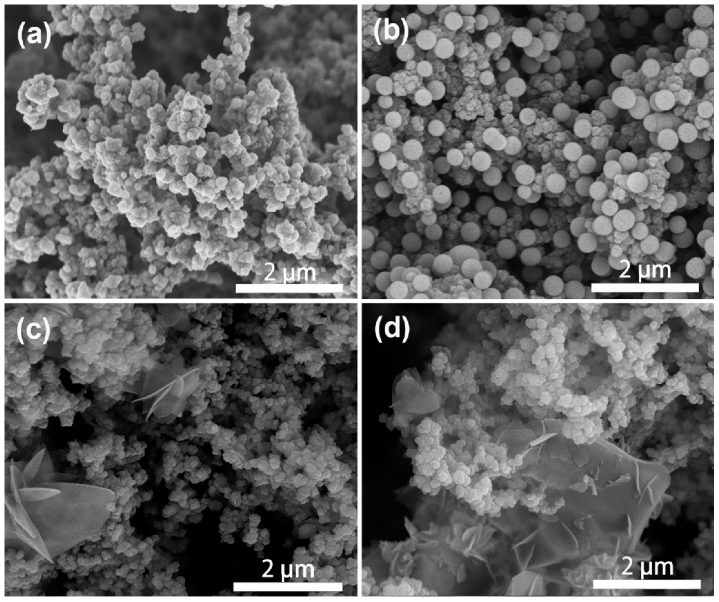
30]. To examine the reactant concentration of HSB on the morphological structures of the final HSB and PPy-HSB composites, both HSB-0.3, HSB-1.2, HSB-1.8 and their PPy-based composites were characterized by SEM, with results shown in
Figure S2 and
Figure 5, respectively. With the increase of hydrazine hydrate and glyoxal in the HSB synthesis process, the morphology of HSB gradually turns from spheres to flakes.
The growth mechanism of HSB, as well as PPy/HSB composites, can be proposed as in
Figure S3. The simple structure and good symmetry of HSB make it easy to arrange in a regular manner, thus forming a dense, stacked structure. However, since its main chain contains carbon and nitrogen double bonds that cannot be rotated, it does not resemble the helical chain conformation of olefins. HSB crystallizes in a chain-axis parallel arrangement, with chemical bonding along with the c-axis and van der Waals forces acting along with the
a and
b-axis, which makes the structure anisotropic. HSB forms the basic structural unit of spherical crystals by orderly arrangement of stacked folded chain wafers, and in order to reduce the surface energy, they tend to grow in all directions with certain crystal nuclei as the center, thus develo** into spherical aggregates with diameters around 500 nm (
Figure S2a). The parallel arrangement causes the HSB polymer to crystallize without cubic crystal system, as evidenced by
Figure S4a, from which it is clear that both PPy and PPy/HSB-0.6 show amorphous states.
According to experimental confirmation [
31], polymer crystal growth occurs only on the sides of the sheet crystals, i.e., in the two-dimensional direction, and the thickness of the wafer remains constant. The concentration of HSB around the wafer increases as the concentration of the reacting monomer increases or the molar ratio changes, but the wafer growth rate varies due to the different HSB concentrations in the wafer, and the wafer growth is more vigorous in some directions at the end of the reaction. Thus, the morphological structure of HSB gradually changes from spheres to a folded structure, as shown in
Figure S2c,d. The XRD result in
Figure S4 also shows the increase in the number of characteristic peaks. This is because as the HSB reaction concentration increases, it allows the HSB to stretch in more places where it is easy to grow in an orientation. This corresponds to the results observed in the SEM observation. Compared with spherical structures, the folded flake structures could increase the specific surface area and improve the multiple scattering of the incident electromagnetic waves, but it destroys the conjugate structure of PPy and makes the conductive network ineffective, which would lead to poor absorption performance.
3.3. Electromagnetic Properties
The electromagnetic absorption capacity of a MAM is generally evaluated by reflection loss (
RL), which can be achieved through the TML equation [
3,
8],
Here, Z
in is the input impedance of the MAM and Z
0 is the characteristic impedance of free space with a value of 120π Ω. Z
in can be obtained from the electromagnetic parameters as follows [
3],
where
f is the frequency,
c is the speed of electromagnetic wave in free space and
d is the thickness of the sample.
μr and
εr are the relative complex magnetic permeability and dielectric permittivity. Generally,
μr and
εr can be written as
μr =
μ′ −j
μ″ and
εr =
ε′ −j
ε″, respectively.
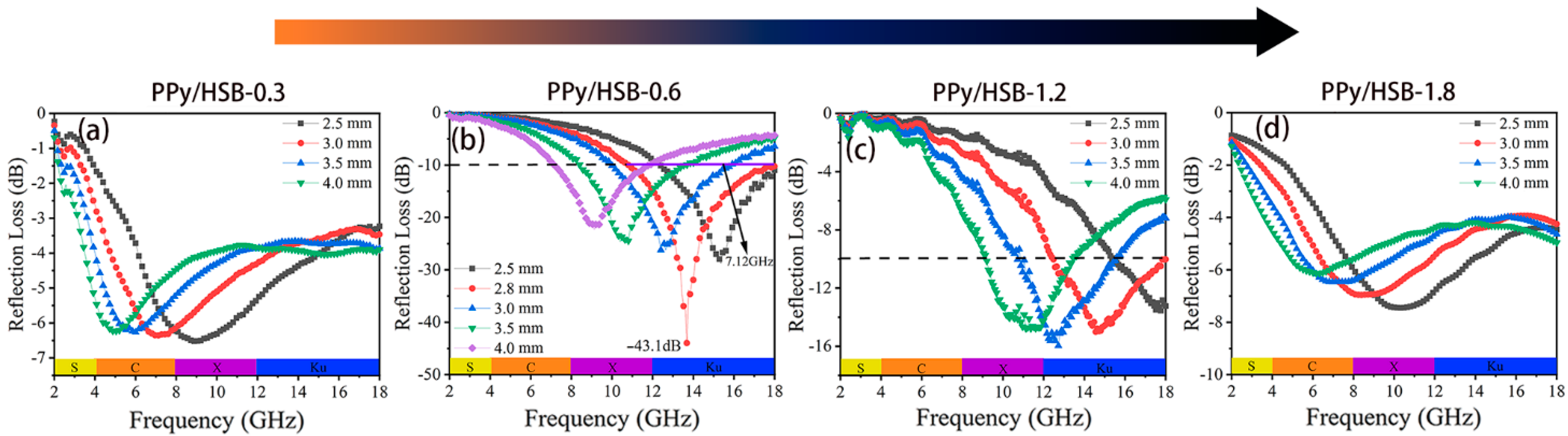
Figure 6 shows the
RL curves of PPy/HSB composites with different concentrations of HSB. It is clear that the concentrations of HSB reactants have an important effect on the EMW absorption properties. When the concentration of HSB is greater than 1.2, there is no effective absorption in the whole frequency range. However, the EMW absorption performance of PPy/HSB composites was significantly improved at lower HSB concentrations. In particular, the maximum
RL value for PPy/HSB-0.6 can reach −43.1 dB at 2.8 mm, and its EAB is as high as 7.12 GHz (10.76−17.88 GHz). With the increase of sample thickness, the absorption peak gradually shifts to lower frequencies, and its effective absorption bandwidth varies in the frequency region of 7.1−17.88 GHz, indicating that the absorption capability of PPy/HSB-0.6 can be modulated by just tuning the matching thickness. Comparatively, PPy and HSB-0.6 only exhibit
RL values inferior to −10 dB, as in
Figure S5. This is due to an impedance mismatching caused by their dielectric being too high or too low, as shown in
Figure S5. The obtained PPy/HSB composites possess more superior microwave absorption properties than most previously reported PPy-based absorbers, even at a smaller thickness, as shown in
Table 1.
In order to further reveal the absorption mechanism of the PPy/HSB composites, their magnetic loss, dielectric loss and impedance matching are analyzed comprehensively. In general, the dissipation of the incident microwave is composed of dielectric loss and magnetic loss. PPy is a typical dielectric material with negligible magnetic loss. Therefore, dielectric loss is considered as the main attenuation mechanism of PPy/HSB complexes.
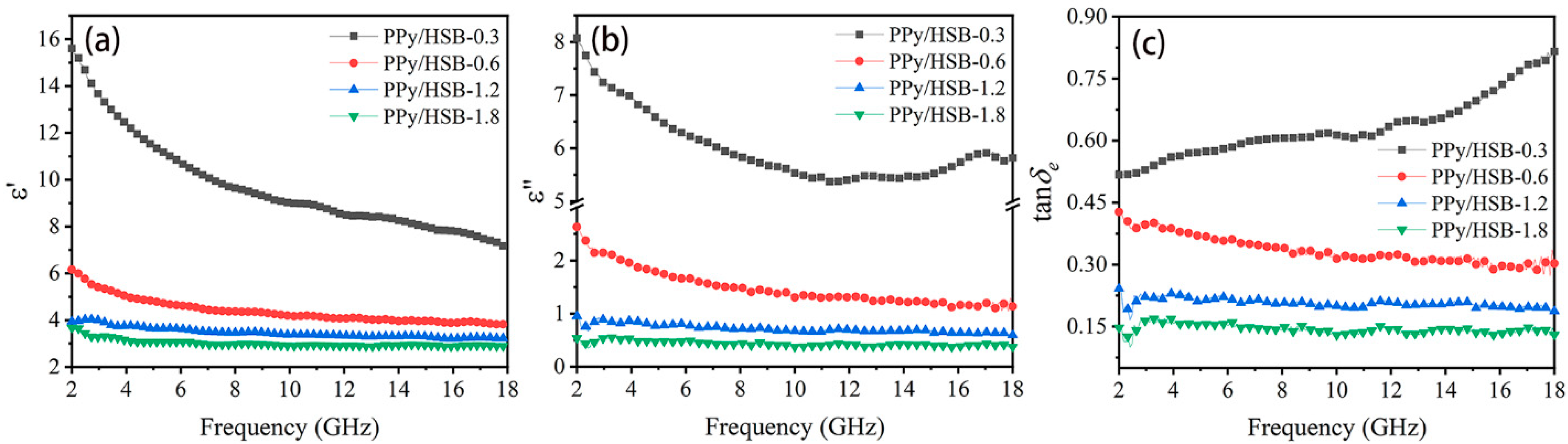
Figure 7 shows the variation of electromagnetic parameters
vs frequency for the composites. The
ε′,
ε″, as well as the dielectric loss tangents (tan
δe =
ε″/
ε′) of PPy/HSB turn smaller with the increasing frequency throughout the frequency range. It is noteworthy that PPy/HSB-0.6 exhibits the highest
ε′ and
ε″ values, indicating its highest dielectric loss properties. As the HSB content increases, the dielectric loss decreases because the introduction of HSB destroys the conductive network of PPy. It thus indicates that the dielectric properties of PPy can be tuned conveniently through changing the contents of HSB components.
As is known, dielectric loss mainly consists of two key factors, i.e., polarization loss and conduction loss [
11,
37,
38,
39]. Since PPy is a typical dielectric medium, dielectric polarization is a critical factor that affects the microwave absorption performance. In general, dielectric polarization comes from molecular polarization, atomic polarization, ionic polarization, space charge polarization (with carriers), electron polarization (inner and valence electrons) and dipole polarization (isoelectric positive and negative charge pairs with non-coincident centers) [
1,
40]. The main polarization modes in GHz frequency are induced polarization and orientation polarization, with orientation polarization playing a dominant role in the attenuation of electromagnetic waves.
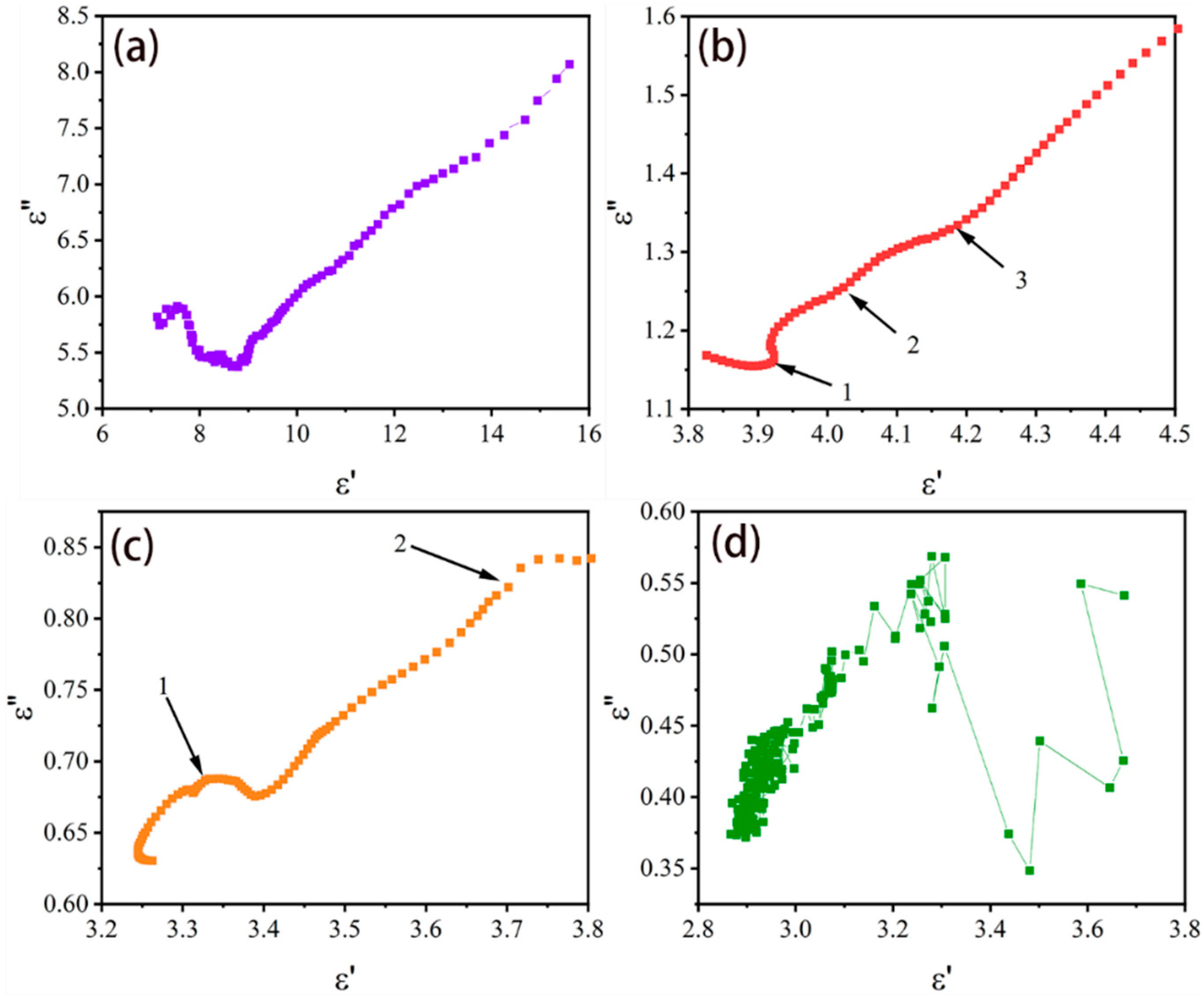
To further explain the dielectric polarization of the PPy/HSB composites, a Cole-Cole semicircle based on the Debye relaxation is introduced, as shown in Equation (3).
where
εs and
ε∞ are the static dielectric constant and dielectric constant in ultimate frequency, respectively [
3]. These semicircles represent the dielectric relaxation processes corresponding to Debye relaxation [
41,
42,
43] and each semicircle represents a polarization behavior [
44]. Both PPy/HSB-0.6 and PPy/HSB-1.2 show several Cole-Cole semicircles, as exhibited in
Figure 8, indicating there exist complicated polarization mechanisms. The semicircle for PPy/HSB-1.8 and PPy/HSB-2.4 are found to be distorted in
Figure 8c,d, indicating that there may be some other processes such as dipole polarization and Maxwell-Wagner relaxation existing in the systems [
45].
Doped PPy has carriers, polaritons and bipolaritons [
46,
47]. When the incident wave comes in contact with PPy, the positive and negative charges of polaritons and dipoles of PPy are separated [
48]. The carriers of PPy are excited to generate holes and electrons, leading to dipole polarization and the consumption of electromagnetic waves. For a dielectric material, the different polarity or conductivity of the components on both sides of the interface would cause the charge accumulation at the interface of the two phases under the action of electric field, thus resulting in interfacial polarization. PPy exhibits a cauliflower-like structure, which gives it a high specific surface area and provides conditions for the uniform dispersion of HSB. Therefore, sufficient interfaces can bring about abundant interfacial polarization and thus dissipate more electromagnetic waves.
In addition to dipole polarization and interfacial polarization, conduction loss is also an important factor affecting the absorption characteristics of PPy/HSB composites. The relationship between electrical conductivity (
σ) and
ε″ is given as follows [
49],
Here,
ε0 (= 8.8542 × 10
−12 F/m) is the dielectric constant in vacuum and
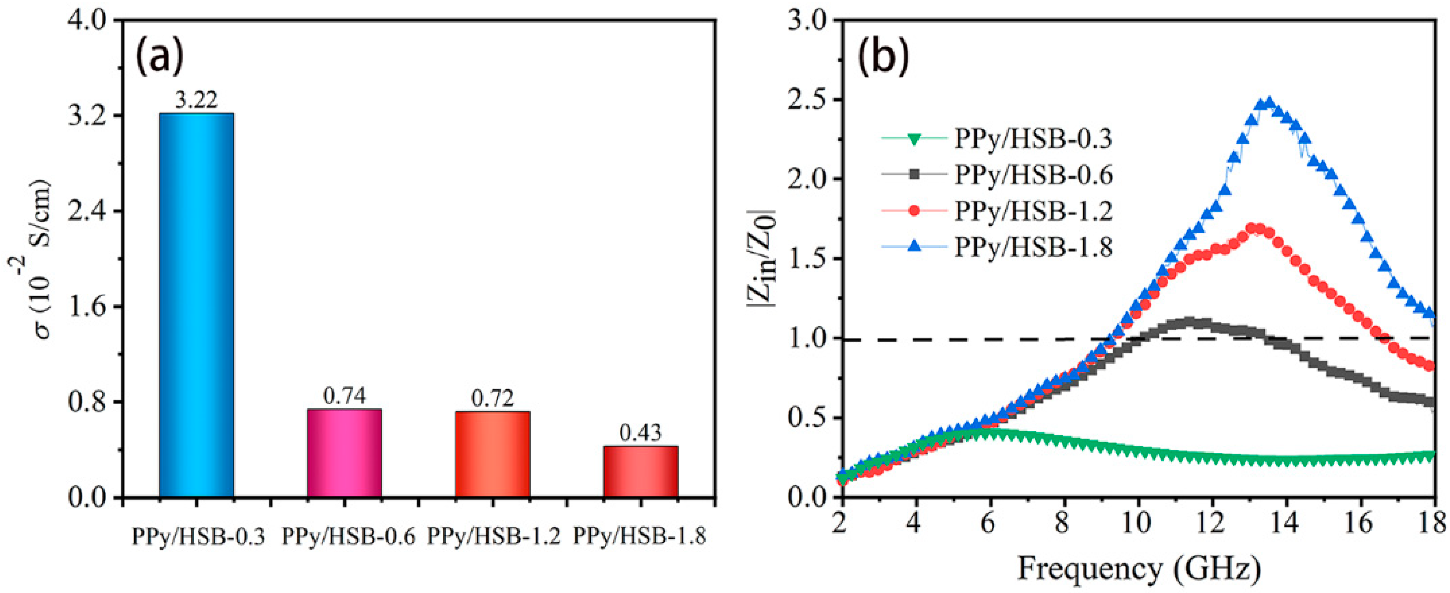
f is the frequency. As can be seen in
Figure 9a, the conductivity gradually decreases as the HSB concentration increases. Generally, EMW absorbing material with high performance needs to meet two fundamental requirements. The first one is that the electromagnetic waves should enter the interior of the material and not be reflected directly by the surface. In other words, a good impedance matching condition is needed to obtain a good microwave absorption performance. The second requirement is that the MAM must have appropriate attenuation property, i.e., higher conductivity or dielectric loss to transfer the incident microwave energy to other sorts, such as heat energy. Generally, a higher conductivity makes the material more capable of losing electromagnetic waves [
50]. However, a much higher conductivity would lead to a strong reflection at the surface of the MAM and thus deteriorate its impedance matching. In this sense, the conductivity must be considered comprehensively with the impedance matching of the MAM.
Figure 9b plots the impedance matching ratios (
z = |Z
in/Z
0|) of the PPy/HSB composites. It is clear that
z increases with the HSB concentrations, which is in inverse trend with electrical conductivity. As is illustrated in Equations (1) and (2), the balance of permeability and conductivity (increasing the permeability or decreasing the conductivity) can achieve good matching. As the concentration of HSB increases, the permittivity decreases but the permeability keeps constant (
Figure S6) without obvious changes, which makes the impedance matching unbalanced.
From
Figure 9a, the electrical conductivity of PPy/HSB-0.6 and PPy/HSB-1.2 are nearly the same, but their
RL values are very different. From
Figure 9b, the value of |Z
in/Z
0| for PPy/HSB-0.6 is close to 1, whereas the |Z
in/Z
0| for PPy/HSB-1.2 is much worse, which explains the phenomenon that PPy/HSB-1.2 has dielectric properties as high as tan
δe = 0.2, but still exhibits poor EMW absorption performance. The impedance matching conditions of PPy/HSB-0.3 and PPy/HSB-1.8 are even worse, due to the low or high concentration of HSB, which makes the conductive network of PPy broken. The above analysis shows that the excellent microwave absorption performance of PPy/HSB-0.6 comes not only from a good loss mechanism but also from a good impedance matching condition, both of which can be adjusted by introducing HSB into PPy powder.
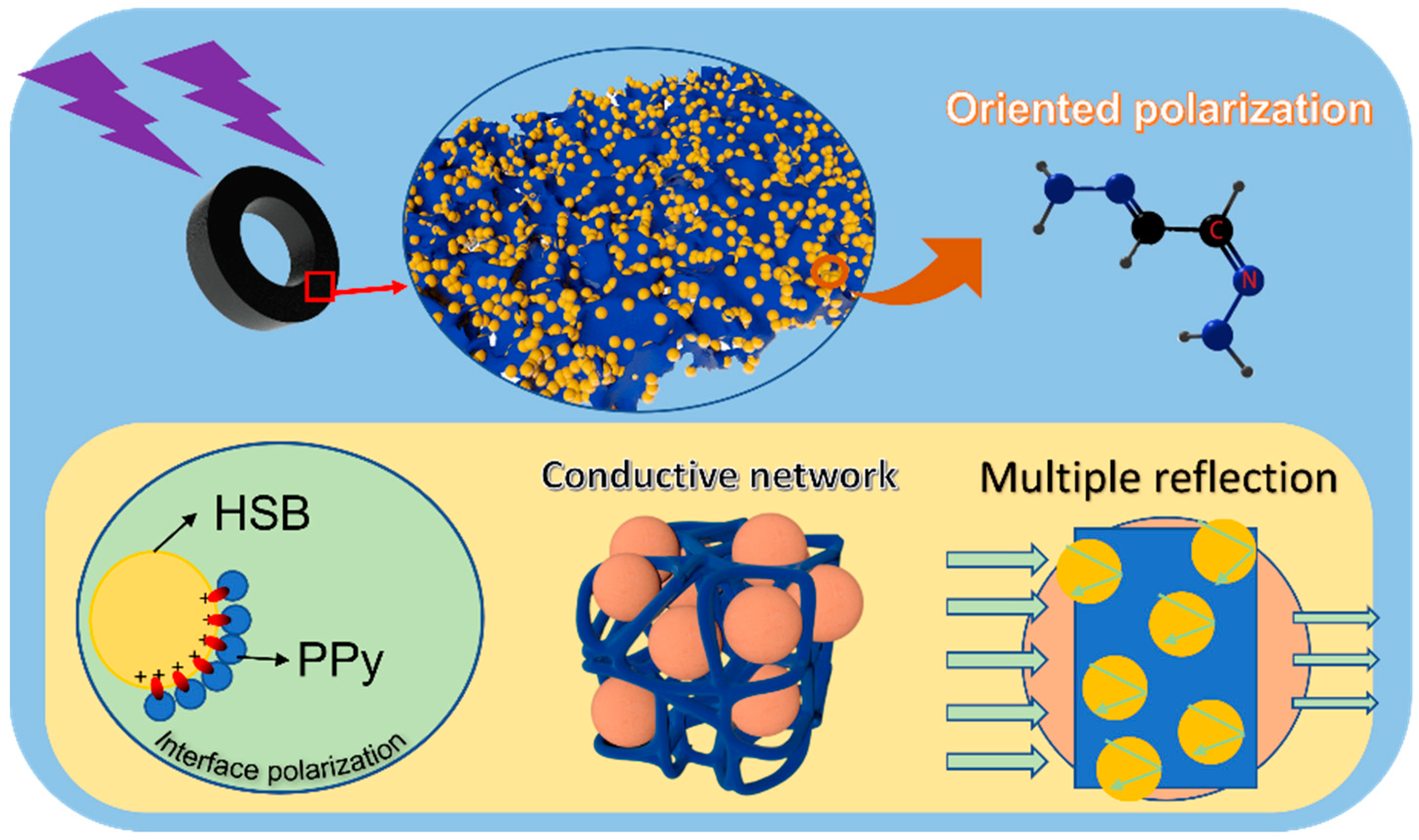
The EMW absorption mechanism of the PPy/HSB-based composites can be interpreted schematically in
Figure 10. Firstly, the composite of conductive PPy and spherical HSB can expand the interface and increase the interfacial polarization. The polarization and related relaxation contribute greatly to the attenuation of the incident wave energy. Secondly, the conjugated structure of PPy makes it easy for electrons to flow and form a conductive network. The resulting induced current can convert the incident electromagnetic wave into other forms of energy for consumption. Finally, the introduction of HSB not only improves the impedance matching of PPy, but also makes it generate multiple dielectric polarization under electric field excitation due to the C=N polar structure therein. The carbon and nitrogen double bond structure in HSB makes itself a permanent dipole moment and results in electromagnetic energy loss when the EMW inters the material [
39]. Moreover, the addition of HSB increases the multi-reflection and scattering of electromagnetic waves in the material, which increases the energy consumption and thus leads to the enhancement of absorption. Therefore, the electromagnetic absorption performance of PPy/HSB-0.6 can be improved and the PPy/HSB based composites can be considered as a potential candidate for electromagnetic absorption materials.


